


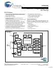

CY7C67200
Document #: 38-08014 Rev. *G Page 4 of 78
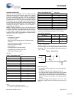
UART Features
• Supports baud rates of 900 to 115.2K
•8-N-1
UART Pins
I
2
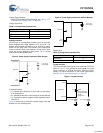
C EEPROM Interface
EZ-OTG provides a master-only I2C interface for external se-
rial EEPROMs. The serial EEPROM can be used to store ap-
plication-specific code and data. This I2C interface is only to
be used for loading code out of EEPROM, it is not a general
I2C interface. The I2C EEPROM interface is a BIOS imple-
mentation and is exposed through GPIO pins. Refer to the
BIOS documentation for additional details on this interface.
I
2
C EEPROM Features
• Supports EEPROMs up to 64 KB (512K bit)
• Auto-detection of EEPROM size
I
2
C EEPROM Pins
Serial Peripheral Interface
EZ-OTG provides an SPI interface for added connectivity.
EZ-OTG may be configured as either an SPI master or SPI
slave. The SPI interface can be exposed through GPIO pins
or the External Memory port.
SPI Features
• Master or slave mode operation
• DMA block transfer and PIO byte transfer modes
• Full duplex or half duplex data communication
• 8-byte receive FIFO and 8-byte transmit FIFO
• Selectable master SPI clock rates from 250 kHz to 12 MHz
• Selectable master SPI clock phase and polarity
• Slave SPI signaling synchronization and filtering
• Slave SPI clock rates up to 2 MHz
• Maskable interrupts for block and byte transfer modes
• Individual bit transfer for non-byte aligned serial communi-
cation in PIO mode
• Programmable delay timing for the active/inactive master
SPI clock
• Auto or manual control for master mode slave select signal
• Complete access to internal memory
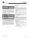
SPI Pins
The SPI port has a few different pin location options as shown
in Table 7. The pin location is selectable via the GPIO Control
register [0xC006].
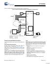
High-Speed Serial Interface
EZ-OTG provides an HSS interface. The HSS interface is a
programmable serial connection with baud rate from 9600
baud to 2M baud. The HSS interface supports both byte and
block mode operations as well as hardware and software
handshaking. Complete control of EZ-OTG can be accom-
plished through this interface via an extensible API and com-
munication protocol. The HSS interface can be exposed
through GPIO pins or the External Memory port.
HSS Features
• 8-bit, no parity code
• Programmable baud rate from 9600 baud to 2M baud
• Selectable 1- or 2-stop bit on transmit
• Programmable intercharacter gap timing for Block Transmit
• 8-byte receive FIFO
• Glitch filter on receive
• Block mode transfer directly to/from EZ-OTG internal
memory (DMA transfer)
• Selectable CTS/RTS hardware signal handshake protocol
• Selectable XON/XOFF software handshake protocol
• Programmable Receive interrupt, Block Transfer Done
interrupts
• Complete access to internal memory
HSS Pins
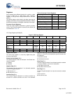
Table 5. UART Interface Pins
Pin Name Pin Number
TX B5
RX B4
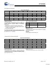
Table 6. I
2
C EEPROM Interface Pins
Pin Name Pin Number
SMALL EEPROM
SCK H3
SDA F3
LARGE EEPROM
SCK F3
SDA H3
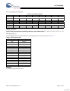
Table 7. SPI Interface Pins
Pin Name Pin Number
nSSI F6 or C6
SCK D5
MOSI D4
MISO C5
Table 8. HSS Interface Pins
Pin Name Pin Number
CTS F6
RTS E4
RX E5
TX E6
[+] Feedback