


CY7C67200
Document #: 38-08014 Rev. *G Page 38 of 78
Device n Frame Number Register [R]
• Device 1 Frame Number Register 0xC092
• Device 2 Frame Number Register 0xC0B2
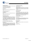
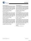
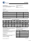
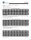
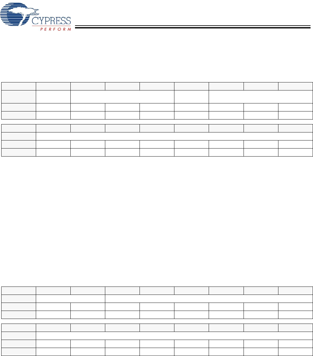
Figure 38. Device n Frame Number Register
Register Description
The Device n Frame Number register is a read only register
that contains the Frame number of the last SOF packet
received. This register also contains a count of SOF/EOP
Timeout occurrences.
SOF/EOP Timeout Flag (Bit 15)
The SOF/EOP Timeout Flag bit indicates when an SOF/EOP
Timeout Interrupt occurs.
1: An SOF/EOP Timeout interrupt occurred
0: An SOF/EOP Timeout interrupt did not occur
SOF/EOP Timeout Interrupt Counter (Bits [14:12])
The SOF/EOP Timeout Interrupt Counter field increments by
1 from 0 to 7 for each SOF/EOP Timeout Interrupt. This field
resets to 0 when a SOF/EOP is received. This field is only
updated when the SOF/EOP Timeout Interrupt Enable bit in
the Device n Interrupt Enable register is set.
Frame (Bits [10:0])
The Frame field contains the frame number from the last
received SOF packet in full speed mode. This field has no
function for low-speed mode. If a SOF Timeout occurs, this
field contains the last received Frame number.
Device n SOF/EOP Count Register [W]
• Device 1 SOF/EOP Count Register 0xC094
• Device 2 SOF/EOP Count Register 0xC0B4
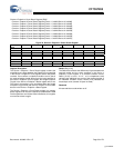
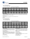
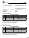
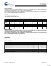
Figure 39. Device n SOF/EOP Count Register
Register Description
The Device n SOF/EOP Count register must be written with
the time expected between receiving a SOF/EOPs. If the
SOF/EOP counter expires before an SOF/EOP is received, an
SOF/EOP Timeout Interrupt can be generated. The SOF/EOP
Timeout Interrupt Enable and SOF/EOP Timeout Interrupt
Flag are located in the Device n Interrupt Enable and Status
registers, respectively.
The SOF/EOP count must be set slightly greater than the
expected SOF/EOP interval. The SOF/EOP counter decre-
ments at a 12-MHz rate. Therefore in the case of an expected
1-ms SOF/EOP interval, the SOF/EOP count must be set
slightly greater then 0x2EE0.
Count (Bits [13:0])
The Count field contains the current value of the SOF/EOP
down counter. At power-up and reset, this value is set to
0x2EE0 and for expected 1-ms SOF/EOP intervals, this
SOF/EOP count should be increased slightly.
Reserved
All reserved bits must be written as ‘0’.
Bit # 15 14 13 12 11 10 9 8
Field
SOF/EOP
Timeout Flag
SOF/EOP
Timeout Interrupt Counter
Reserved Frame...
Read/Write R R R R - R R R
Default 0 0 0 0 0 0 0 0
Bit # 7 6 5 4 3 2 1 0
Field ...Frame
Read/Write R R R R R R R R
Default 0 0 0 0 0 0 0 0
Bit # 15 14 13 12 11 10 9 8
Field Reserved Count...
Read/Write - - R R R R R R
Default 0 0 1 0 1 1 1 0
Bit # 7 6 5 4 3 2 1 0
Field ...Count
Read/Write R R R R R R R R
Default 1 1 1 0 0 0 0 0
[+] Feedback