


CY7C67200
Document #: 38-08014 Rev. *G Page 19 of 78
Port A D+ Status (Bit 13)
The Port A D+ Status bit is a read-only bit that indicates the
value of DATA+ on Port A.
1: D+ is high
0: D+ is low
Port A D– Status (Bit 12)
The Port A D– Status bit is a read-only bit that indicates the
value of DATA– on Port A.
1: D– is high
0: D– is low
LOA (Bit 10)
The LOA bit selects the speed of Port A.
1: Port A is set to Low-speed mode
0: Port A is set to Full-speed mode
Mode Select (Bit 9)
The Mode Select bit sets the SIE for host or device operation.
When set for device operation only one USB port is supported.
The active port is selected by the Port Select bit in the Host n
Count Register.
1: Host mode
0: Device mode
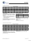
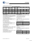
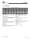
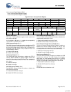
Port A Resistors Enable (Bit 7)
The Port A Resistors Enable bit enables or disables the
pull-up/pull-down resistors on Port A. When enabled, the
Mode Select bit and LOA bit of this register sets the
pull-up/pull-down resistors appropriately. When the Mode
Select is set for Host mode, the pull-down resistors on the data
lines (D+ and D–) are enabled. When the Mode Select is set
for Device mode, a single pull-up resistor on either D+ or D–,
determined by the LOA bit, will be enabled. See Ta ble 23 for
details.
1: Enable pull-up/pull-down resistors
0: Disable pull-up/pull-down resistors
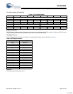
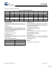
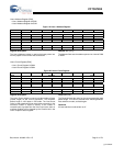
Port A Force D± State (Bits [4:3])
The Port A Force D± State field controls the forcing state of the
D+ D– data lines for Port A. This field forces the state of the
Port A data lines independent of the Port Select bit setting. See
Table 24 for details.
Suspend Enable (Bit 2)
The Suspend Enable bit enables or disables the suspend
feature on both ports. When suspend is enabled the USB
transceivers are powered down and can not transmit or
received USB packets but can still monitor for a wakeup
condition.
1: Enable suspend
0: Disable suspend
Port A SOF/EOP Enable (Bit 0)
The Port A SOF/EOP Enable bit is only applicable in host
mode. In Device mode this bit must be written as ‘0’. In host
mode this bit enables or disables SOFs or EOPs for Port A.
Either SOFs or EOPs will be generated depending on the LOA
bit in the USB n Control Register when Port A is active.
1: Enable SOFs or EOPs
0: Disable SOFs or EOPs
Reserved
All reserved bits must be written as ‘0’.
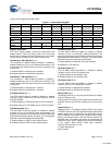
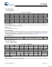
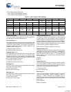
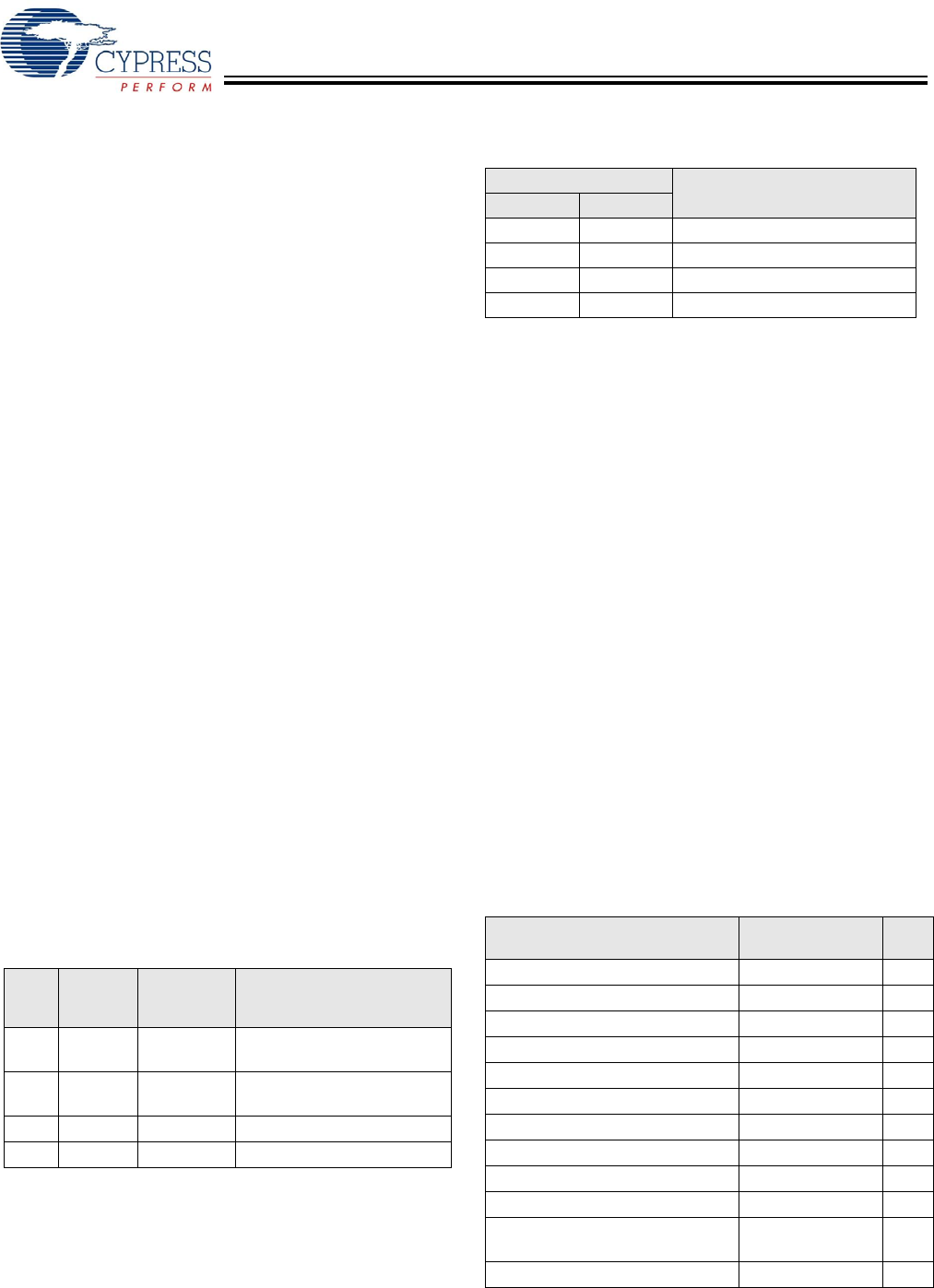
USB Host Only Registers
There are twelve sets of dedicated registers to USB host only
operation. Each set consists of two identical registers (unless
otherwise noted); one for Host Port 1 and one for Host Port 2.
These register sets are covered in this section and summa-
rized in Table 25.
Table 23.USB Data Line Pull-up and Pull-down Resistors
L0A
Mode
Select
Port n
Resistors
Enable
Function
X X 0 Pull up/Pull down on D+ and
D– Disabled
X 1 1 Pull down on D+ and D–
Enabled
1 0 1 Pull up on USB D– Enabled
0 0 1 Pull up on USB D+ Enabled
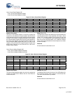
Table 24.Port A Force D± State
Port A Force D± State
Function
MSB LSB
0 0 Normal Operation
0 1 Force USB Reset, SE0 State
1 0 Force J-State
1 1 Force K-State
Table 25.USB Host Only Register
Register Name
Address
(Host 1/Host 2)
R/W
Host n Control Register 0xC080/0xC0A0 R/W
Host n Address Register 0xC082/0xC0A2 R/W
Host n Count Register 0xC084/0xC0A4 R/W
Host n Endpoint Status Register 0xC086/0xC0A6 R
Host n PID Register 0xC086/0xC0A6 W
Host n Count Result Register 0xC088/0xC0A8 R
Host n Device Address Register 0xC088/0xC0A8 W
Host n Interrupt Enable Register 0xC08C/0xC0AC R/W
Host n Status Register 0xC090/0xC0B0 R/W
Host n SOF/EOP Count Register 0xC092/0xC0B2 R/W
Host n SOF/EOP Counter
Register
0xC094/0xC0B4 R
Host n Frame Register 0xC096/0xC0B6 R
[+] Feedback