CY7C67200
Document #: 38-08014 Rev. *G Page 59 of 78
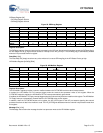
Data Ready bit of the SPI Control register is set to ‘1’. Writing to this register in PIO byte mode will initiate a transfer of data, the
number of bits defined by Transmit Bit Length field in the SPI Control register.
Data (Bits [7:0])
The Data field contains data received or to be transmitted on the SPI port.
Reserved
All reserved bits must be written as ‘0’.
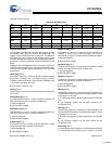
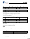
SPI Transmit Address Register [0xC0D8] [R/W]
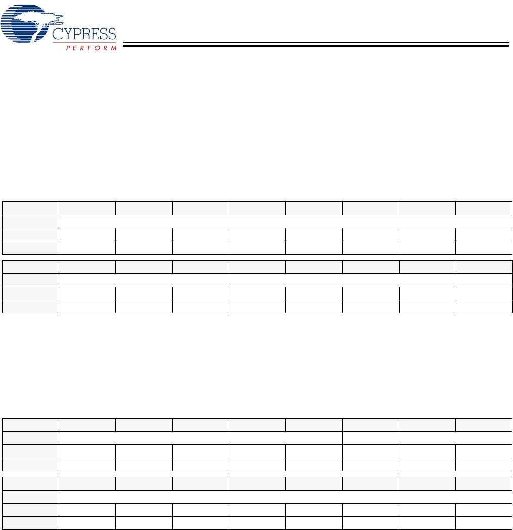
Figure 69. SPI Transmit Address Register
Register Description
The SPI Transmit Address register is used as the base address for the SPI transmit DMA.
Address (Bits [15:0])
The Address field sets the base address for the SPI transmit DMA.
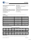
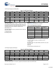
SPI Transmit Count Register [0xC0DA] [R/W]
Figure 70. SPI Transmit Count Register
Register Description
The SPI Transmit Count register designates the block byte length for the SPI transmit DMA transfer.
Count (Bits [10:0])
The Count field sets the count for the SPI transmit DMA transfer.
Reserved
All reserved bits must be written as ‘0’.
Bit # 15 14 13 12 11 10 9 8
Field Address...
Read/Write R/W R/W R/W R/W R/W R/W R/W R/W
Default 0 0 0 0 0 0 0 0
Bit # 7 6 5 4 3 2 1 0
Field ...Address
Read/Write R/W R/W R/W R/W R/W R/W R/W R/W
Default 0 0 0 0 0 0 0 0
Bit # 15 14 13 12 11 10 9 8
Field Reserved Count...
Read/Write - - - - - R/W R/W R/W
Default 0 0 0 0 0 0 0 0
Bit # 7 6 5 4 3 2 1 0
Field ...Count
Read/Write R/W R/W R/W R/W R/W R/W R/W R/W
Default 0 0 0 0 0 0 0 0
[+] Feedback


