


CY7C67200
Document #: 38-08014 Rev. *G Page 36 of 78
Device n Address Register [W]
• Device 1 Address Register 0xC08E
• Device 2 Address Register 0xC0AE
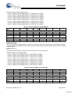
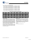
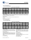
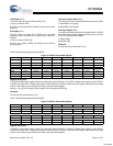
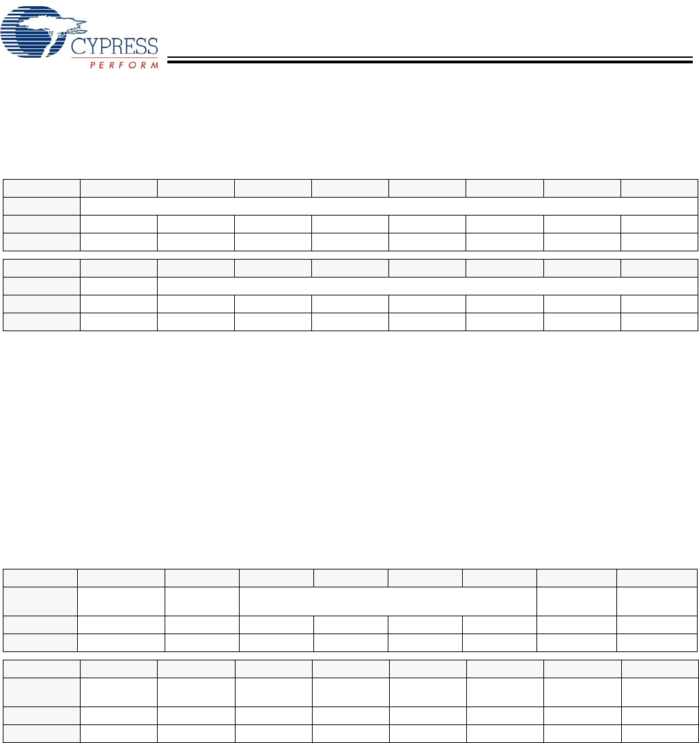
Figure 36. Device n Address Register
Register Description
The Device n Address register holds the device address assigned by the host. This register initializes to the default address 0 at
reset but must be updated by firmware when the host assigns a new address. Only USB data sent to the address contained in
this register will be responded to, all others are ignored.
Address (Bits [6:0])
The Address field contains the USB address of the device assigned by the host.
Reserved
All reserved bits must be written as ‘0’.
Device n Status Register [R/W]
• Device 1 Status Register 0xC090
• Device 2 Status Register 0xC0B0
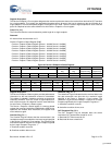
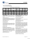
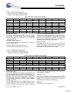
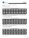
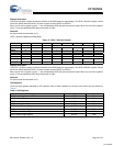
Figure 37. Device n Status Register
Register Description
The Device n Status register provides status information for
device operation. Pending interrupts can be cleared by writing
a ‘1’ to the corresponding bit. This register can be accessed
by the HPI interface.
VBUS Interrupt Flag (Bit 15)
The VBUS Interrupt Flag bit indicates the status of the OTG
VBUS interrupt (only for Port 1A). When enabled this interrupt
triggers on both the rising and falling edge of VBUS at 4.4V.
This bit is only available for Device 1 and is a reserved bit in
Device 2.
1: Interrupt triggered
0: Interrupt did not trigger
ID Interrupt Flag (Bit 14)
The ID Interrupt Flag bit indicates the status of the OTG ID
interrupt (only for Port 1A). When enabled this interrupt
triggers on both the rising and falling edge of the OTG ID pin.
This bit is only available for Device 1 and is a reserved bit in
Device 2.
1: Interrupt triggered
0: Interrupt did not trigger
SOF/EOP Interrupt Flag (Bit 9)
The SOF/EOP Interrupt Flag bit indicates if the SOF/EOP
received interrupt has triggered.
1: Interrupt triggered
0: Interrupt did not trigger
Bit # 15 14 13 12 11 10 9 8
Field Reserved...
Read/Write - - - - - - - -
Default 0 0 0 0 0 0 0 0
Bit # 7 6 5 4 3 2 1 0
Field ...Reserved Address
Read/Write - W W W W W W W
Default 0 0 0 0 0 0 0 0
Bit # 15 14 13 12 11 10 9 8
Field
VBUS
Interrupt Flag
ID Interrupt
Flag
Reserved SOF/EOP
Interrupt Flag
Reset
Interrupt Flag
Read/Write R/W R/W - - - - R/W R/W
Default X X X X X X X X
Bit # 7 6 5 4 3 2 1 0
Field
EP7 Interrupt
Flag
EP6 Interrupt
Flag
EP5 Interrupt
Flag
EP4 Interrupt
Flag
EP3 Interrupt
Flag
EP2 Interrupt
Flag
EP1 Interrupt
Flag
EP0 Interrupt
Flag
Read/Write R/W R/W R/W R/W R/W R/W R/W R/W
Default X X X X X X X X
[+] Feedback