


CY7C67200
Document #: 38-08014 Rev. *G Page 26 of 78
Host n Status Register [R/W]
• Host 1 Status Register 0xC090
• Host 2 Status Register 0xC0B0
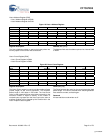
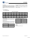
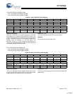
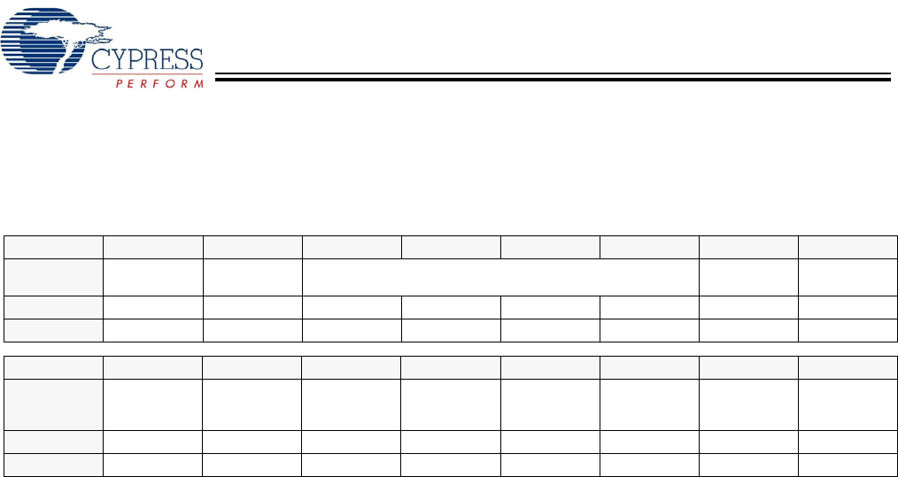
Figure 26. Host n Status Register
Register Description
The Host n Status register provides status information for host
operation. Pending interrupts can be cleared by writing a ‘1’ to
the corresponding bit. This register can be accessed by the
HPI interface.
VBUS Interrupt Flag (Bit 15)
The VBUS Interrupt Flag bit indicates the status of the OTG
VBUS interrupt (only for Port 1A). When enabled this interrupt
triggers on both the rising and falling edge of VBUS at 4.4V.
This bit is only available for Host 1 and is a reserved bit in
Host 2.
1: Interrupt triggered
0: Interrupt did not trigger
ID Interrupt Flag (Bit 14)
The ID Interrupt Flag bit indicates the status of the OTG ID
interrupt (only for Port 1A). When enabled this interrupt
triggers on both the rising and falling edge of the OTG ID pin.
This bit is only available for Host 1 and is a reserved bit in
Host 2.
1: Interrupt triggered
0: Interrupt did not trigger
SOF/EOP Interrupt Flag (Bit 9)
The SOF/EOP Interrupt Flag bit indicates the status of the
SOF/EOP Timer interrupt. This bit triggers ‘1’ when the
SOF/EOP timer expires.
1: Interrupt triggered
0: Interrupt did not trigger
Port A Wake Interrupt Flag (Bit 6)
The Port A Wake Interrupt Flag bit indicates remote wakeup
on Port A.
1: Interrupt triggered
0: Interrupt did not trigger
Port A Connect Change Interrupt Flag (Bit 4)
The Port A Connect Change Interrupt Flag bit indicates the
status of the Connect Change interrupt on Port A. This bit
triggers ‘1’ on either a rising edge or falling edge of a USB
Reset condition (device inserted or removed). Together with
the Port A SE0 Status bit, it can be determined whether a
device was inserted or removed.
1: Interrupt triggered
0: Interrupt did not trigger
Port A SE0 Status (Bit 2)
The Port A SE0 Status bit indicates if Port A is in an SE0 state
or not. Together with the Port A Connect change Interrupt Flag
bit, it can be determined whether a device was inserted
(non-SE0 condition) or removed (SE0 condition).
1: SE0 condition
0: Non-SE0 condition
Done Interrupt Flag (Bit 0)
The Done Interrupt Flag bit indicates the status of the USB
Transfer Done interrupt. The USB Transfer Done triggers
when either the host responds with an ACK, or a device
responds with any of the following: ACK, NAK, STALL, or
Timeout. This interrupt is used for both Port A and Port B.
1: Interrupt triggered
0: Interrupt did not trigger
Bit # 15 14 13 12 11 10 9 8
Field
VBUS
Interrupt Flag
ID Interrupt
Flag
Reserved SOF/EOP
Interrupt Flag
Reserved
Read/Write R/W R/W - - - - R/W -
Default X X X X X X X X
Bit # 7 6 5 4 3 2 1 0
Field
Reserved Port A
Wake Interrupt
Flag
Reserved Port A Connect
Change
Interrupt Flag
Reserved Port A
SE0
Status
Reserved Done
Interrupt Flag
Read/Write - R/W - R/W - R/W - R/W
Default X X X X X X X X
[+] Feedback