


Dell
TM
XFR D630 Fully Rugged Notebook Service Manual
Page 51 of 106 Revision A01
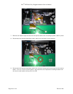
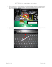
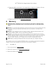
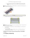
12. Fasten the 2 M2x6 screws shown in the image below to complete the installation of the top
metal bracket.
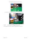
13. Replace the hinge cover (see
104H
Installing the Hinge Cover
).
9 Memory
CAUTION: Before you begin any of the procedures in this section, follow the safety
instructions in the XFR D630 Product Information Guide and in the XFR D630 User’s
Guide.
NOTICE: To avoid electrostatic discharge, ground yourself by using a wrist grounding strap or by
periodically touching an unpainted metal surface (such as a connector on the back of the
computer).
NOTICE: If your computer has only one memory module, install the memory module in the
connector labeled "DIMM A," which is underneath the keyboard.
NOTICE: If you remove your original memory modules from the computer during a memory
upgrade, keep them separate from any new modules that you may have, even if you purchased
the new modules from Dell. If possible, do not pair an original memory module with a new
memory module. Otherwise, your computer may not function at optimal performance.
NOTE: Memory modules purchased from Dell are covered under your computer warranty.
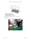
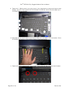
Your computer has two user-accessible SODIMM sockets, one accessed from beneath the keyboard
(DIMM A), and the other accessed from the bottom of the computer (DIMM B).
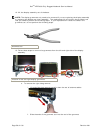
9.1 DIMM A
1. Follow the procedures in
105H
Before You Begin
.
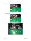
2. Remove the hinge cover (see
106H
Removing the Hinge Cover
).
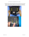
3. Remove the keyboard (see
107H
Keyboards
).