


Dell
TM
XFR D630 Fully Rugged Notebook Service Manual
Page 65 of 106 Revision A01
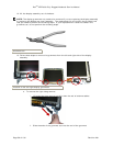
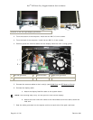
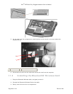
6. For the optional Touch Screen displays, pull the touch controller cable through the rubber
grommet in the antenna cable assembly on the left side hinge. These antenna cables are part
of the back cover assembly and must be separated from the touch controller cable to allow for
the removal of the Display Panel.
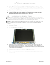
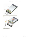
7. Lift the display panel a few inches from the display back cover.
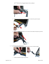
8. Draw the LED ribbon-cable release tab away from the display panel to release the ribbon
cable, and lift the display panel fully from the display back cover.
10.6 Installing the Display Panel
NOTE: Remove the replacement display panel assembly from its packaging. The new part will
have packing material covering the LVDS connector. The LVDS cable will be taped to the back of
the panel on top of the copper foil backing so care is needed during tape removal.
NOTE: For optional Touch Screen Display panels, the touch controller cable is also taped to the
back of the panel on top of the copper foil backing, and similar care is needed during tape
removal.
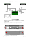
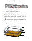
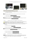
1. Connect the LED cable.
2. Align the display panel in the top cover.
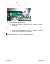
3. Check cable routing on each side of the inverter. On the right side, verify LVDS cable and
antenna cables are correctly placed to exit the top cover as shown. On the left side, verify
antenna cables and touch controller cable (for touch screen Displays only) are correctly placed
to exit the top cover as shown above.
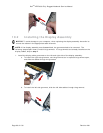
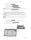
4. Route cables into the grommets on each side using the grommet tool.
5. Align grommet on each side with top cover edge, to seal the opening where cables exit the
Display Assembly.