


Dell
TM
XFR D630 Fully Rugged Notebook Service Manual
Page 89 of 106 Revision A01
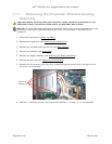
7. Remove the processor thermal-cooling assembly (see
215H
Removing the Processor Thermal-
Cooling Assembly
).
NOTICE: When removing the processor, pull it straight up. Be careful not to bend the pins on the
processor.
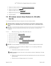
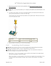
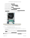
8. To loosen the ZIF socket, use a small, flat-blade screwdriver and rotate the ZIF-socket cam
screw counterclockwise until it comes to the cam stop.
The ZIF-socket cam screw secures the processor to the system board. Take note of the arrow
on the ZIF-socket cam screw.
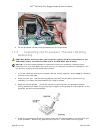
1
processor
2
pin-1 corner of processor
3
ZIF socket
4
ZIF-socket cam screw
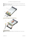
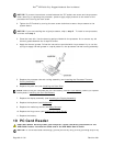
9. Use a processor extraction tool to remove the processor.
18.2 Installing the Processor
NOTICE: Ensure that the cam lock is in the fully open position before seating the processor.
Seating the processor properly in the ZIF socket does not require force.
NOTICE: A processor that is not properly seated can result in an intermittent connection or
permanent damage to the processor and ZIF socket.
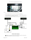
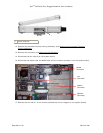
1. Align the pin-1 corner of the processor so that it points to the triangle on the system board,
and insert the processor into the ZIF socket.
When the processor is correctly seated, all four corners are aligned at the same height. If one
or more corners of the processor are higher than the others, the processor is not seated
correctly.