


Dell
TM
XFR D630 Fully Rugged Notebook Service Manual
Page 63 of 106 Revision A01
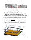
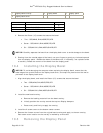
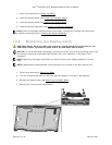
1
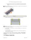
display bezel overlay
2
display bezel
3
display panel
4
display back cover
PART NUMBER
SCREW TYPE
QUANTITY
18428
CSK SCREW M2 X 8-BLACK
2
18417
PAN HEAD SCREW M2 X 12-BLACK
7
18114
SHOULDER SCREW M2.5
6
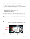
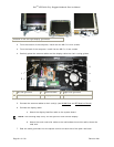
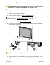
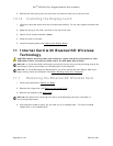
4. Remove the fifteen (15) screws that secure the bezel:
• Two - SCR,M2X8,PHH,MSCR,ZPS,XFR
• Seven - SCR,M2X12,PHH,MSCR,ZPS,XFR
• Six - SCR,M2.5X10,PHH,MSCR,SHLDR,XFR
NOTICE: Carefully separate the bezel from the display back cover to avoid damage to the bezel.
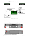
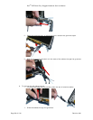
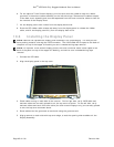
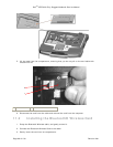
5. Starting from the outside edges of the bezel, use your fingers to gently pry the bezel upward
from the display panel. Release the sides of the bezel next; if necessary, use a plastic scribe
to carefully release the corners of the bezel from the display panel.
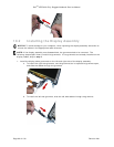
10.4 Installing the Display Bezel
NOTICE: To avoid damaging the computer when replacing the display bezel, ensure that the
bezel edges line up with those on the display back cover, and snap into place around the entire
perimeter of the display back cover.
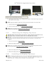
1. Align the display bezel, and install the fifteen (15) screws that secure the bezel:
• Two - SCR,M2X8,PHH,MSCR,ZPS,XFR
• Seven - SCR,M2X12,PHH,MSCR,ZPS,XFR
• Six - SCR,M2.5X10,PHH,MSCR,SHLDR,XFR
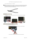
2. Install the new bezel overlay.
a. Remove the backing material from the bezel overlay.
b. Initially position the overlay around the top two Display bumpers.
c. Press evenly and firmly to apply the overlay.
3. Install the 2 screw covers to the bottom center screws.
4. Remove the 8 screw covers from the original bezel overlay and apply to the new overlay.
Each screw cover location on the overlay is marked by a white dot.
10.5 Removing the Display Panel