


Chapter 4 Parameters|
4-74 Revision August 2008, 2ELE, V1.02
07.09
Reserved
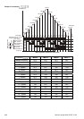
07.10 Accumulative Motor Operation Time (Min.) Unit: 1
Settings 0~1439 Factory Setting: 0
07.11 Accumulative Motor Operation Time (Day) Unit: 1
Settings 0 ~65535 Factory Setting: 0
Pr.07.10 and Pr.07.11 are used to record the motor operation time. They can be cleared by
setting to 0 and time is less than 1 minute is not recorded.
07.12 Motor PTC Overheat Protection Unit: 1
Factory Setting: 0
Settings 0 Disable
1 Enable
07.14 Motor PTC Overheat Protection Level Unit: 0.1
Settings 0.1~10.0V Factory Setting: 2.4
When the motor is running at low frequency for a long time, the cooling function of the motor
fan will be lower. To prevent overheating, it needs to have a Positive Temperature Coefficient
thermoistor on the motor and connect its output signal to the drive’s corresponding control
terminals.
When the source of first/second frequency command is set to AVI (02.00=1/02.09=1), it will
disable the function of motor PTC overheat protection (i.e. Pr.07.12 cannot be set to 1).
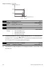
If temperature exceeds the setting level, motor will be coast to stop and
is
displayed. When the temperature decreases below the level of (Pr.07.15-Pr.07.16) and
stops blinking, you can press RESET key to clear the fault.
Pr.07.14 (overheat protection level) must exceed Pr.07.15 (overheat warning level).
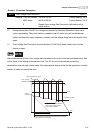
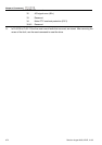
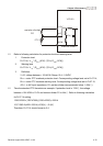
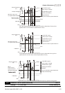
The PTC uses the AVI-input and is connected via resistor-divider as shown below.
1. The voltage between +10V to ACM: lies within 10.4V~11.2V.
2. The impedance for AVI is around 47kΩ.
3. Recommended value for resistor-divider R1 is 1~10kΩ.
4. Please contact your motor dealer for the curve of temperature and resistance value for
PTC.