


Chapter 2 Installation and Wiring|
Revision August 2008, 2ELE, V1.02 2-9
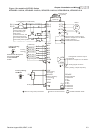
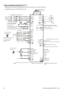
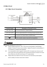
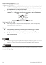
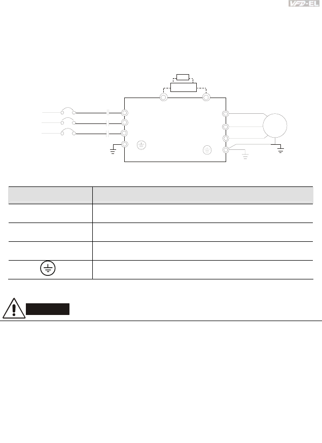
2.3 Main Circuit
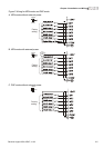
2.3.1 Main Circuit Connection
R(L1)
S(L2)
T(L3)
R
S
T
U(T1)
V(T2)
W(T3)
IM
3~
MC
E
E
+
-
No fuse breaker
(NFB)
Brake Resistor(Optional)
Motor
BUE
BR
Brake Unit
(Optional)
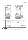
Terminal Symbol Explanation of Terminal Function
R/L1, S/L2, T/L3
AC line input terminals (1-phase/3-phase)
U/T1, V/T2, W/T3
AC drive output terminals for connecting 3-phase induction motor
+, -
Connections for External Brake unit (BUE series)
Earth connection, please comply with local regulations.
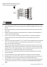
CAUTION!
Mains power terminals (R/L1, S/L2, T/L3)
Connect these terminals (R/L1, S/L2, T/L3) via a non-fuse breaker or earth leakage
breaker to 3-phase AC power (some models to 1-phase AC power) for circuit protection. It
is unnecessary to consider phase-sequence.
It is recommended to add a magnetic contactor (MC) in the power input wiring to cut off
power quickly and reduce malfunction when activating the protection function of AC motor
drives. Both ends of the MC should have an R-C surge absorber.
Please make sure to fasten the screw of the main circuit terminals to prevent sparks
which is made by the loose screws due to vibration.