


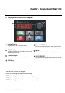
Chapter 2 Installation and Wiring|
2-12 Revision August 2008, 2ELE, V1.02
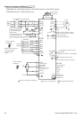
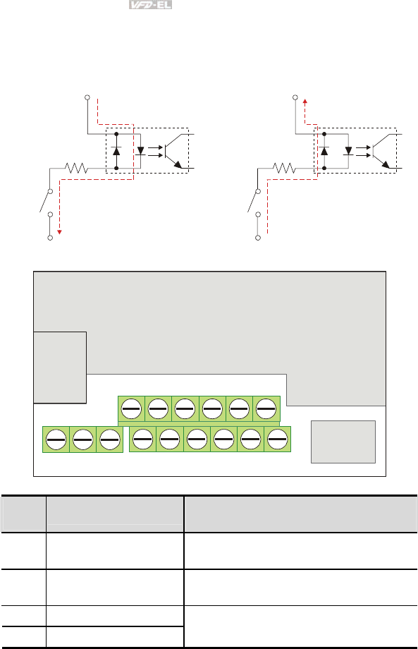
2.4 Control Terminals
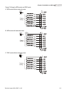
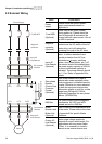
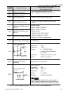
Circuit diagram for digital inputs (NPN current 16mA.)
+24V
DCM
NPN Mode
1
3
4
2
2
1
+24V
DCM
PNP Mode
1
3
4
2
2
1
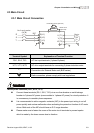
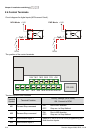
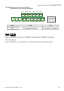
The position of the control terminals
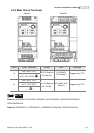
RS-485
10VMI1 MI3 MI524V AVI
RA
RB
RC
MI2 MI4 MI6 DCM ACMAFM
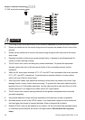
Terminal symbols and functions
Terminal
Symbol
Terminal Function
Factory Settings (NPN mode)
ON: Connect to DCM
MI1 Forward-Stop command
ON: Run in MI1 direction
OFF: Stop acc. to Stop Method
MI2 Reverse-Stop command
ON: Run in MI2 direction
OFF: Stop acc. to Stop Method
MI3 Multi-function Input 3
MI4 Multi-function Input 4
Refer to Pr.04.05 to Pr.04.08 for programming the
Multi-function Inputs.