


Chapter 4 Parameters|
Revision August 2008, 2ELE, V1.02 4-103
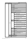
10.09 Treatment of the Erroneous Feedback Signals (for PID feedback error)
Factory Setting: 0
Settings 0 Warning and RAMP to stop
1 Warning and COAST to stop
2 Warning and keep operating
This function in only for ACI signal.
AC motor drive action when the feedback signals (analog PID feedback) are abnormal
according to Pr.10.16.
10.10
Gain Over the PID Detection Value
Unit: 0.1
Settings
0.0 to 10.0
Factory Setting: 1.0
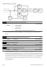
This is the gain adjustment over the feedback detection value. Refer to PID control block
diagram in Pr.10.06 for detail.
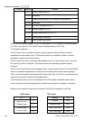
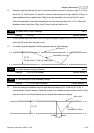
10.12 PID Feedback Level Unit: 0.1
Settings 1.0 to 50.0% Factory Setting: 10.0
10.13 Detection Time of PID Feedback Unit: 0.1
Settings 0.1 to 300.0 sec Factory Setting: 5.0
This parameter is used to set detection of the offset between set point and feedback.
When the offset is higher than (the setting of Pr.10.12 X Pr.01.00) for a time exceeding the
setting of Pr.10.13, the AC motor drive will output a signal when Pr.03.00 is set to 16 and will
act according to Pr.10.20.
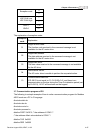
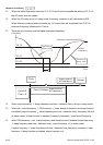
10.14 Sleep/Wake Up Detection Time Unit: 0.1
Settings 0.0 to 6550 sec Factory Setting: 0.0
10.15 Sleep Frequency Unit: 0.01
Settings 0.00 to 600.0 Hz Factory Setting: 0.00
10.16 Wakeup Frequency Unit: 0.01
Settings 0.00 to 600.0 Hz Factory Setting: 0.00
When the actual output frequency
≤
Pr.10.15 and the time exceeds the setting of Pr.10.14,
the AC motor drive will be in sleep mode.