


Chapter 2 Installation and Wiring|
2-10 Revision August 2008, 2ELE, V1.02
Please use voltage and current within the regulation shown in Appendix A.
When using a GFCI (Ground Fault Circuit Interrupter), select a current sensor with
sensitivity of 200mA, and not less than 0.1-second detection time to avoid nuisance
tripping. For specific GFCI of the AC motor drive, please select a current sensor with
sensitivity of 30mA or above.
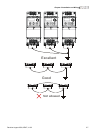
Do NOT run/stop AC motor drives by turning the power ON/OFF. Run/stop AC motor
drives by RUN/STOP command via control terminals or keypad. If you still need to
run/stop AC drives by turning power ON/OFF, it is recommended to do so only ONCE per
hour.
Do NOT connect 3-phase models to a 1-phase power source.
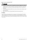
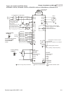
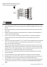
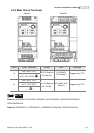
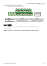
Output terminals for main circuit (U, V, W)
The factory setting of the operation direction is forward running. The method to control the
operation direction is to set by the communication parameters. Please refer to the group 9
for details.
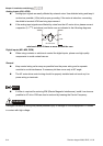
When it needs to install the filter at the output side of terminals U/T1, V/T2, W/T3 on the
AC motor drive. Please use inductance filter. Do not use phase-compensation capacitors
or L-C (Inductance-Capacitance) or R-C (Resistance-Capacitance), unless approved by
Delta.
DO NOT connect phase-compensation capacitors or surge absorbers at the output
terminals of AC motor drives.
Use well-insulated motor, suitable for inverter operation.
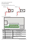
Terminals [+, -] for connecting brake resistor
All VFD-EL series don’t have a built-in brake chopper. Please connect an external
optional brake unit (BUE-series) and brake resistor. Refer to BUE series user manual for
details.
When not used, please leave the terminals [+, -] open.