


Chapter 4 Parameters|
Revision August 2008, 2ELE, V1.02 4-85
09.03
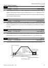
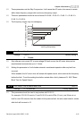
Time-out Detection
Unit: 0.1
Settings 0.0 to 120.0 sec Factory Setting: 0.0
0.0 Disable
If Pr.09.03 is not equal to 0.0, Pr.09.02=0~2, and there is no communication on the bus during
the Time Out detection period (set by Pr.09.03), “cE10” will be shown on the keypad.
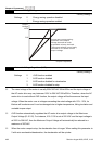
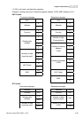
09.04 Communication Protocol
Factory Setting: 0
Settings 0 Modbus ASCII mode, protocol <7,N,2>
1 Modbus ASCII mode, protocol <7,E,1>
2 Modbus ASCII mode, protocol <7,O,1>
3 Modbus RTU mode, protocol <8,N,2>
4 Modbus RTU mode, protocol <8,E,1>
5 Modbus RTU mode, protocol <8,O,1>
6 Modbus RTU mode, protocol <8,N,1>
7 Modbus RTU mode, protocol <8,E,2>
8 Modbus RTU mode, protocol <8,O,2>
9 Modbus ASCII mode, protocol <7,N,1>
10 Modbus ASCII mode, protocol <7,E,2>
11 Modbus ASCII mode, protocol <7,O,2>
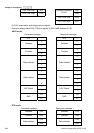
1. Control by PC
A VFD-EL can be set up to communicate in Modbus networks using one of the following
modes: ASCII (American Standard Code for Information Interchange) or RTU (Remote
Terminal Unit). Users can select the desired mode along with the serial port
communication protocol in Pr.09.04.
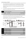
Code Description:
The CPU will be about 1 second delay when using communication reset. Therefore, there
is at least 1 second delay time in master station.
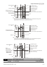
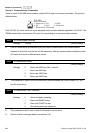
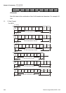
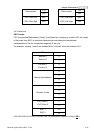
ASCII mode:
Each 8-bit data is the combination of two ASCII characters. For example, a 1-byte data:
64 Hex, shown as ‘64’ in ASCII, consists of ‘6’ (36Hex) and ‘4’ (34Hex).
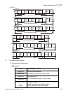
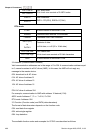
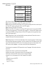
Character ‘0’ ‘1’ ‘2’ ‘3’ ‘4’ ‘5’ ‘6’ ‘7’
ASCII code 30H 31H 32H 33H 34H 35H 36H 37H