


Appendix B Accessories|
Revision August 2008, 2ELE, V1.02 B-3
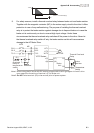
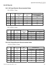
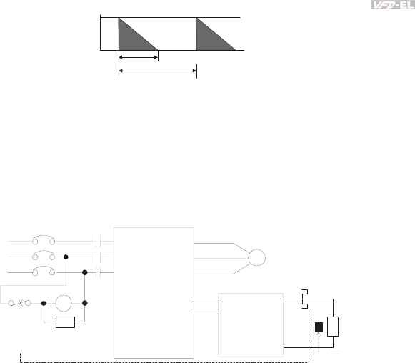
100%
T0
T1
Braking Time
Cycle Time
ED% = T1/T0x100(%)
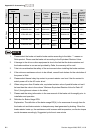
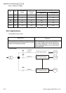
9. For safety reasons, install a thermal overload relay between brake unit and brake resistor.
Together with the magnetic contactor (MC) in the mains supply circuit to the drive it offers
protection in case of any malfunctioning. The purpose of installing the thermal overload
relay is to protect the brake resistor against damage due to frequent brake or in case the
brake unit is continuously on due to unusual high input voltage. Under these
circumstances the thermal overload relay switches off the power to the drive. Never let
the thermal overload relay switch off only the brake resistor as this will cause serious
damage to the AC Motor Drive.
R/L1
S/L2
T/L3
NFB
MC
VFD Series
MOTOR
O.L.
U/T1
V/T2
W/T3
+P
-N
()
()
B1
B2
SA
R/L1
S/L2
T/L3
MC
IM
BR
O.L.
Thermal
Overload
Relay or
temperature
switch
Surge
Absorber
Thermal Overload
Relay
Brake
Resistor
Brake
Unit
+P
-N
()
()
Note1: When using the AC drive with DC reactor, please refer to wiring diagram in the AC drive
user manual for the wiring of terminal +(P) of Brake unit.
Note2: wire terminal -(N) to the neutral point of power system.Do NOT
Temperature
Switch