


Chapter 2 Installation and Wiring|
2-4 Revision August 2008, 2ELE, V1.02
AVI/ACI
ACM
+
+10V
5K
3
2
1
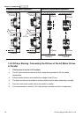
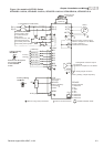
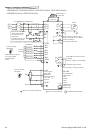
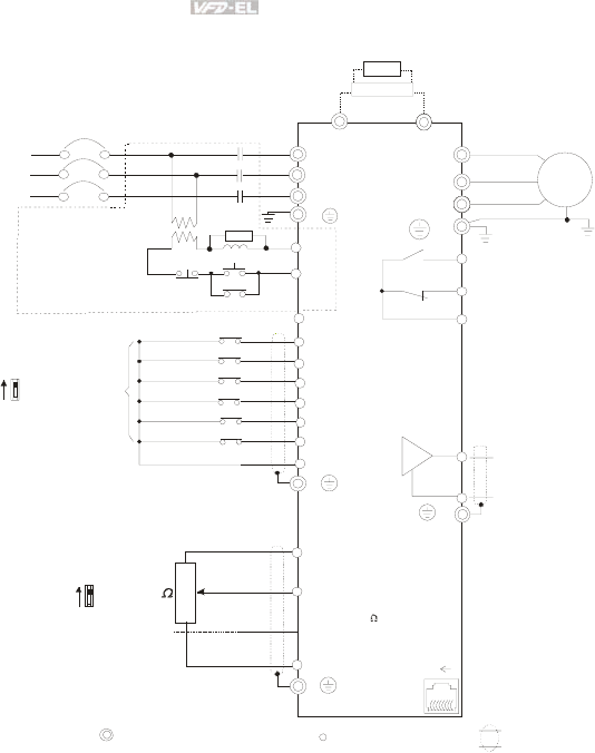
Figure 2 for models of VFD-EL Series
VFD002EL23A, VFD004EL23A/43A, VFD007EL23A/43A, VFD015EL23A/43A,
VFD022EL23A/43A, VFD037EL23A/43A
Power supply
+10V/3mA
Master Frequency
0-10V 47K
/4-20mA
Analog Signal Common
E
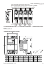
Main circuit (power) terminals
Control circuit terminals
Shielded leads & Cable
E
R(L1)
S(L2)
Fuse/NFB(No Fuse Breaker)
SA
OFF
ON
MC
MC
RB
RC
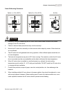
Recommended Circuit
when power supply
is turned OFF by a
fault output.
If the fault occurs, the
contact will be ON to
turn off the power and protect the power system.
R(L1)
S(L2)
E
Analog Multi-function Output
Terminal
Refer to chapter 2.4 for details.
U(T1)
V(T2)
W(T3)
IM
3~
AFM
ACM
RA
RB
RC
Motor
Analog Signal common
E
E
MI1
MI2
MI3
MI4
MI6
MI5
DCM
+24V
FWD/Stop
REV/Stop
Multi-step 1
Multi-step 2
Multi-step 3
Multi-step 4
Digital Signal Common
Factory
setting
AVI
ACI
Factory setting:
AVI Mode
-
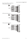
RS-485
Serial interface
1: Reserved
2: EV
5: SG+
6: Reserved
7: Reserved
8:
3: GND
4: SG-
Reserved
8
1
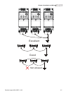
NPN
PNP
Factory setting:
NPN Mode
Please refer to Figure 3
for wiring of NPN
mode and PNP
mode.
BUE
brake unit
(optional)
BR
brake resistor
(optional)
Multi-function contact output
Refer to chapter 2.4 for details.
Factory setting is
malfunction indication
Factory setting: output frequency
T(L3)
T(L3)
Sw1
Sw2