


Chapter 4 Parameters|
4-50 Revision August 2008, 2ELE, V1.02
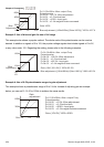
For Example: When using the meter with full scale of 5 volts, adjust Pr.03.04 to 50%. If
Pr.03.03 is set to 0, then 5VDC will correspond to Maximum Output Frequency.
03.05 Terminal Count Value Unit: 1
Settings 0 to 9999 Factory Setting: 0
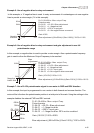
This parameter sets the count value of the internal counter. To increase the internal counter,
one of Pr.04.05 to 04.08 should be set to 12. Upon completion of counting, the specified output
terminal will be activated. (Pr.03.00 set to 10).
When the display shows c555, the drive has counted 555 times. If display shows c555•, it
means that real counter value is between 5,550 and 5,559.
03.06 Preliminary Count Value Unit: 1
Settings 0 to 9999 Factory Setting: 0
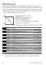
When the counter value reaches this value, the corresponding multi-function output terminal
will be activated, provided one of Pr.03.00set to 11 (Preliminary Count Value Setting). This
multi-function output terminal will be deactivated upon completion of Terminal Count Value
Attained.
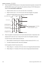
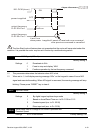
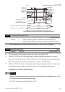
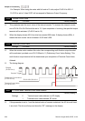
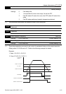
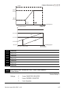
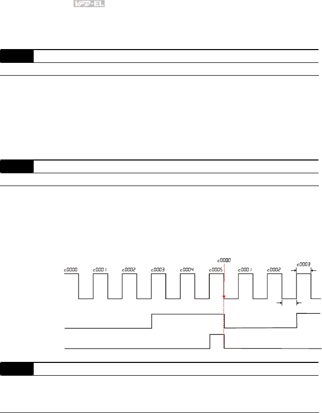
The timing diagram:
Terminal Count Value
(Pr. 03.00=10)
Preliminary Count Value
(Pr. 03.00=11)
Display
(Pr.00.04=1)
TRG
Counter Trigger
The width of trigger signal
should not be less than
2ms(<250 Hz)
2msec
2msec
Ex:03.05=5,03.06=3
03.07 EF Active when Terminal Count Value Attained
Factory Setting: 0
Settings 0 Terminal count value attained, no EF display
1 Terminal count value attained, EF active
If this parameter is set to 1 and the desired value of counter is attained, the AC drive will treat
it as a fault. The drive will stop and show the “EF” message on the display.