


Chapter 4 Parameters|
4-56 Revision August 2008, 2ELE, V1.02
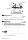
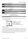
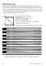
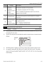
Example 8: Use negative slope
In this example, the use of negative slope is shown. Negative slopes are used in applications for
control of pressure, temperature or flow. The sensor that is connected to the input generates a large
signal (10V) at high pressure or flow. With negative slope settings, the AC motor drive will slow stop
the motor. With these settings the AC motor drive will always run in only one direction (reverse). This
can only be changed by exchanging 2 wires to the motor.
60Hz
0Hz
0V
10V
Pr.01.00=60Hz--Max. output Freq.
Potentiometer
Pr.04.00 =100%--Bias adjustment
Pr.04.01 =0--Positive bias
Pr.04.02 =100%--Input gain
Pr.04.03 =1--Negative bias: REV motion enabled
Gain:(10V/10V)*100%=100%
Bias adjustment:((60Hz/60Hz)/(Gain/100%))*100%=100%
negative slope
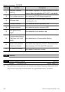
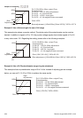
04.11 Minimum AVI Voltage Unit: 0.1
Settings 0.0 to 10.0V Factory Setting: 0.0
04.12 Minimum AVI Frequency (percentage of Pr.01.00) Unit: 0.1
Settings 0.0 to 100.0% Factory Setting: 0.0
04.13 Maximum AVI Voltage Unit: 0.1
Settings 0.0 to 10.0V Factory Setting: 10.0
04.14 Maximum AVI Frequency (percentage of Pr. 01.00) Unit: 0.1
Settings 0.0 to 100.0% Factory Setting: 100.0
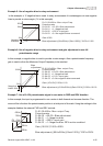
04.15 Minimum ACI Current Unit: 0.1
Settings 0.0 to 20.0mA Factory Setting: 4.0
04.16 Minimum ACI Frequency (percentage of Pr. 01.00) Unit: 0.1
Settings 0.0 to 100.0% Factory Setting: 0.0
04.17 Maximum ACI Current Unit: 0.1
Settings 0.0 to 20.0mA Factory Setting: 20.0
04.18 Maximum ACI Frequency (percentage of Pr. 01.00) Unit: 0.1
Settings 0.0 to 100.0% Factory Setting: 100.0
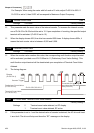
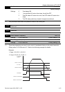
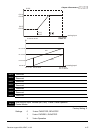
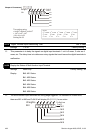
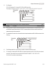
The above parameters are used to set the analog input reference values. The min and max
frequencies are based on Pr.01.00 (during open-loop control) as shown in the following.