


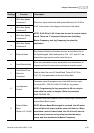
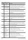
Chapter 4 Parameters|
Revision August 2008, 2ELE, V1.02 4-55
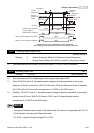
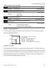
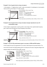
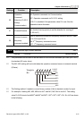
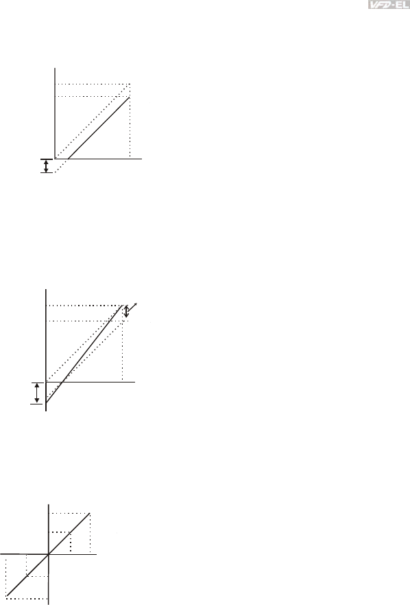
Example 5: Use of negative bias in noisy environment
In this example, a 1V negative bias is used. In noisy environments it is advantageous to use negative
bias to provide a noise margin (1V in this example).
60Hz
0Hz
0V
10V
Pr.01.00=60Hz--Max. output Freq.
Potentiometer
Pr.04.00 =10.0%--Bias adjustment
Pr.04.01 =1--Negative bias
Pr.04.02 =100%--Input gain
Pr.04.03 =0--No negative bias command
Gain:100%
Bias adjustment:((6Hz/60Hz)/(Gain/100%))*100%=10.0%
Negative
bias 6Hz
1V
54Hz
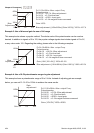
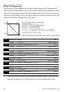
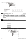
Example 6: Use of negative bias in noisy environment and gain adjustment to use full
potentiometer range
In this example, a negative bias is used to provide a noise margin. Also a potentiometer frequency
gain is used to allow the Maximum Output Frequency to be reached.
60Hz
0Hz
0V
10V
Pr.01.00=60Hz--Max. output Freq.
Negative
bias 6.6Hz
1V
Bias
adjustment
Potentiometer
Pr.04.00 =10.0%--Bias adjustment
Pr.04.01 =1--Negative bias
Pr.04.02 =111%--Input gain
Pr.04.03 =0--No negative bias command
Gain:(10V/9V)*100%=111%
Bias adjustment:((6.6Hz/60Hz)/(Gain/100%))*100%=10.0%
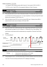
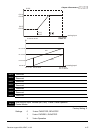
Example 7: Use of 0-10V potentiometer signal to run motor in FWD and REV direction
In this example, the input is programmed to run a motor in both forward and reverse direction. The
motor will be idle when the potentiometer position is at mid-point of its scale. Using the settings in this
example disables the external FWD and REV controls.
Pr.01.00=60Hz--Max. output Freq.
Potentiometer
Pr.04.00 =50.0%--Bias adjustment
Pr.04.01 =1--Negative bias
Pr.04.02 =200%--Input gain
Pr.04.03 =1--Negative bias: REV motion enabled
Gain:(10V/5V)*100%=200%
Bias adjustment:((60Hz/60Hz)/(Gain/100%))*100%=200%
60Hz
30Hz
0Hz
0V
5V
10V
30Hz
60Hz
REV
FWD