


D-Link DES-3250TG Standalone Layer 2 Switch
Section 3
Identifying External Components
Front Panel
Rear Panel
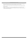
Side Panels
Gigabit Combo Ports
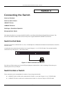
LED Indicators
This chapter describes the front panel, rear panel, side panels, and optional plug-in module, and LED indicators of the
DES-3250TG.
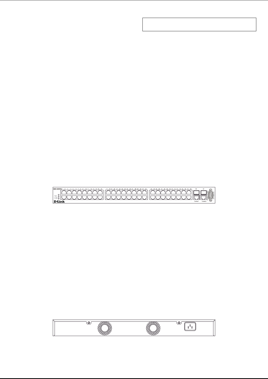
Front Panel
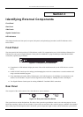
The front panel of the Switch consists of LED indicators, an RS-232 communication port, 48 (10/100 Mbps) Ethernet/Fast
Ethernet ports, and a pair of Gigabit Ethernet Combo ports for 1000BASE-T (plug-in module provided) and Mini GBIC
connections (optional plug-in module).
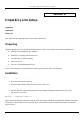
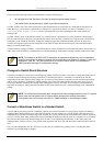
Figure 3-1. Front panel view of the Switch
● Comprehensive LED indicators display the status of the switch and the network (see the LED Indicators section
below).
● An RS-232 DCE console port for setting up and managing the switch via a connection to a console terminal or PC
using a terminal emulation program.
● Forty-eight high-performance NWay Ethernet ports, all of which operate at 10/100 Mbps for connections to end
stations, servers and hubs. All ports can auto-negotiate between 10Mbps or 100Mbps and full or half duplex.
● Two Gigabit Ethernet Combo ports for making 1000BASE-T and Mini GBIC connections.
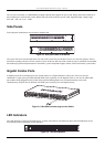
Rear Panel
The rear panel of the switch consists of two fans and an AC power connector.
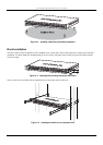
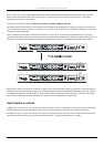
Figure 3-2. Rear panel view of the Switch
The system fans are used to dissipate heat. The sides of the system also provide heat vents to serve the same purpose. Do not
block these openings, and leave at least 6 inches of space at the rear and sides of the switch for proper ventilation. Be reminded
that without proper heat dissipation and air circulation, system components might overheat, which could lead to system failure.
7