


D-Link DES-3250TG Standalone Layer 2 Switch
according to the requirements for the
type of profile.
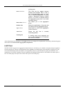
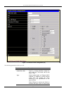
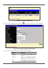
Select Ethernet to instruct the Switch to
examine the layer 2 part of each packet
header.
Select IP to instruct the Switch to
examine the IP address in each frame's
header.
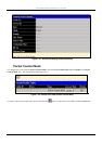
Select Packet Content Mask to specify a
mask to hide the content of the packet
header.
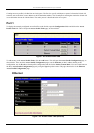
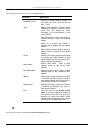
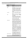
Offset
This field will instruct the Switch to mask
the packet header beginning with the
offset value specified:
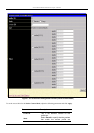
value (0-15) - Enter a value in hex form
to mask the packet from the beginning of
the packet to the 15th byte.
value (16-31) – Enter a value in hex form
to mask the packet from byte 16 to byte
31.
value (32-47) – Enter a value in hex form
to mask the packet from byte 32 to byte
47.
value (48-63) – Enter a value in hex form
to mask the packet from byte 48 to byte
63.
value (64-79) – Enter a value in hex form
to mask the packet from byte 64 to byte
79.
Port
The user may set the Access Profile
Table on a per-port basis by entering an
entry in this field. Entering all will denote
all ports on the Switch. The port list is
specified by listing the lowest switch
number and the beginning port number
on that switch, separated by a colon.
Then the highest switch number, and the
highest port number of the range (also
separated by a colon) are specified. The
beginning and end of the port list range
are separated by a dash. For example,
1:3 specifies switch number 1, port 3. 2:4
specifies switch number 2, port 4. 1:3 -
2:4 specifies all of the ports between
switch 1, port 3 and switch 2, port 4 − in
numerical order.
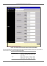
Click Apply to implement changes made.
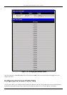
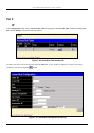
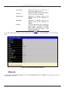
To establish the rule for a previously created Access Profile:
87