


D-Link DES-3250TG Standalone Layer 2 Switch
The AC power connector is a standard three-pronged connector that supports the power cord. Plug-in the female connector of
the provided power cord into this socket, and the male side of the cord into a power outlet. Supported input voltages range
from 100 ~ 240 VAC at 50 ~ 60 Hz.
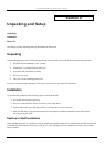
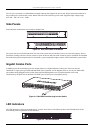
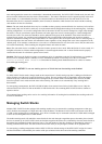
Side Panels
Each side panel contains heat vents to help to dissipate heat.
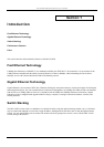
Figure 3-3. Side panel views of the Switch
The system fans are used to dissipate heat. The sides of the system also provide heat vents to serve the same purpose. Do not
block these openings, and leave at least 6 inches of space at the rear and sides of the switch for proper ventilation. Be reminded
that without proper heat dissipation and air circulation, system components might overheat, which could lead to system failure.
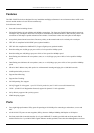
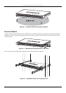
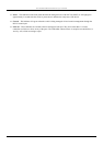
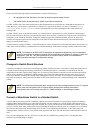
Gigabit Combo Ports
In addition to the 48 10/100 Mbps ports, the Switch features two Gigabit Ethernet Combo ports. These two ports are
1000BASE-T copper ports (provided) and Mini-GBIC ports (optional). See the diagram below to view the two Mini-GBIC
port modules being plugged into the Switch. Please note that although these two front panel modules can be used
simultaneously, the ports must be different. The GBIC port will always have the highest priority.
Figure 3-4. Mini-GBIC modules plug-in to the Switch
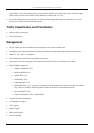
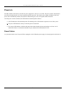
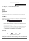
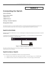
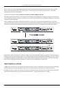
LED Indicators
The LED indicators of the Switch include Power, Console, and Link/Act. The following shows the LED indicators for the
Switch along with an explanation of each indicator.
Figure 3-5. The LED Indicators
8