


D-Link DES-3250TG Standalone Layer 2 Switch
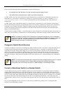
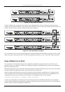
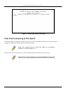
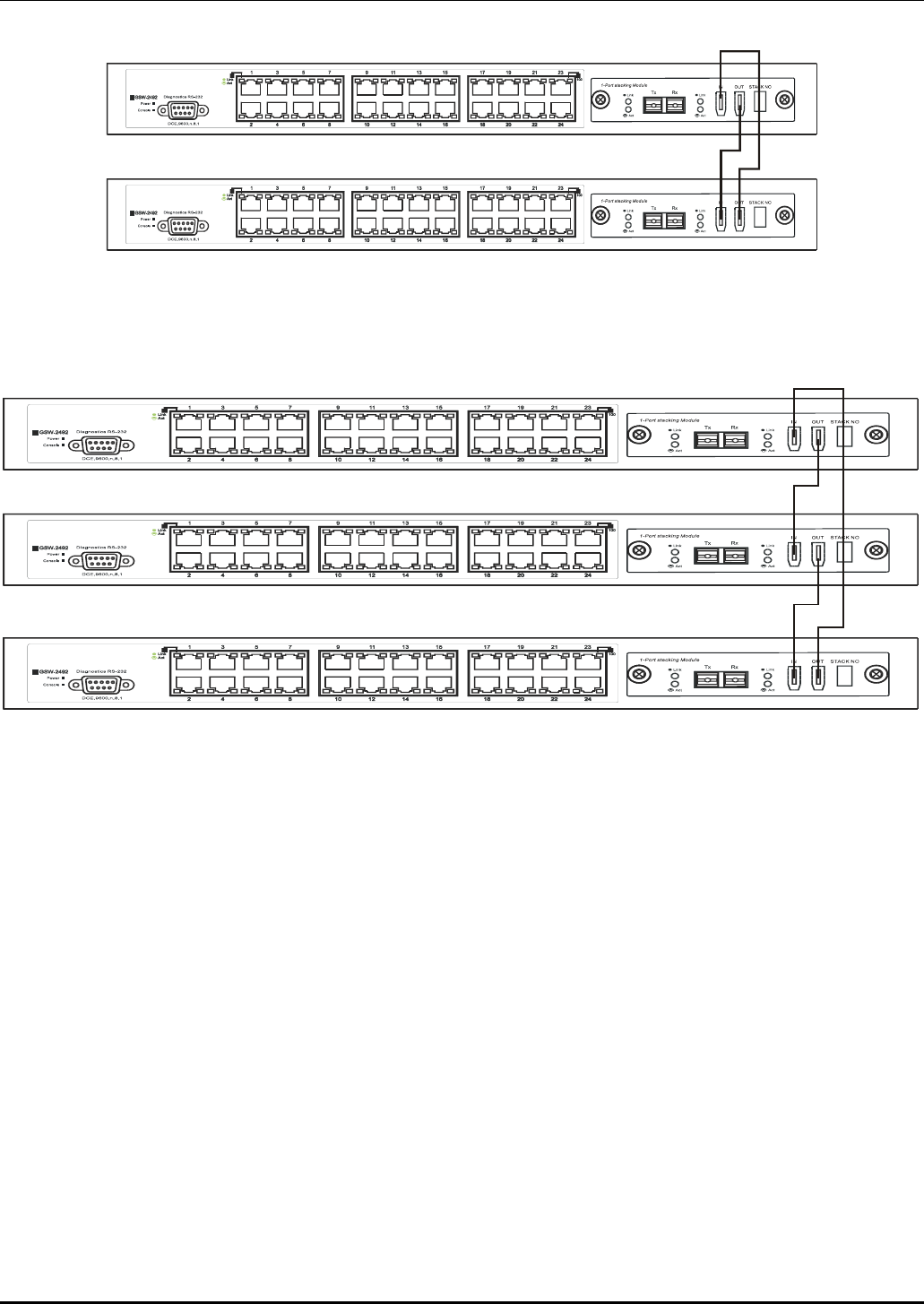
Figure 4- 4. Add a Switch to a Stack
Switch C is added to the existing stack where Switch A is the designated master. Power off all devices and securely place
Switch C in the slot beneath Switch B. Adjust stacking cable connections so the OUT port on Switch B connects the IN port on
Switch C and the OUT port of Switch C connects to the IN port of Switch A.
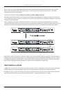
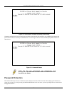
Figure 4- 5. Add a third Switch to a stack
Power on the entire stack. The new stacking arrangement is recognized and the new relationship is negotiated. Switch A retains
status as the master of the stack, Switch C is in auto mode and therefore functions as a slave. The stack is ready for operation.
Swap a Master from a Stack
Let’s assume the stack arrangement in the previous example has a problem that requires the master unit, Switch A, to be
replaced. In this case, we can preserve all the same configuration settings by downloading the previously saved configuration
files to the replacement Switch.
Before disconnecting the network connections of the original master unit, label each Ethernet cable so they can be placed in the
same port number in the replacement Switch. Then remove the device from the rack.
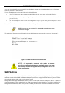
Place the replacement Switch in the same slot. Power on the new Switch and attach a console cable to it. Configure the new
unit to be a master and save the settings. Connect the Ethernet cable needed to access the TFTP server containing the saved
configuration files of the previous master unit. Download the saved configuration files, use the command:
download configuration <ipaddr> <path_filename>
Save the new settings and power off the Switch. Now the stacking connections and Ethernet connections can be completed
exactly as before. Reconnect the stacking cables and Ethernet connections and power on the entire stack. The stack should now
function as before with all the configuration settings intact.
15