


D-Link DES-3250TG Standalone Layer 2 Switch
Since we want to keep the same IP address and all the other settings on the standalone Switch, this Switch will become the
master of the stack and Switch B will become the slave. To make sure Switch A functions as the master we will enable
stacking and override the auto function.
Use the CLI to enter the command:
config stacking mode enable master
The stacking mode for Switch B is set to the default auto-stacking mode and therefore no changes are required. Switch B will
lose configuration settings including its IP settings, so if you want to save these be sure to upload the configuration files before
making the stacking connection.
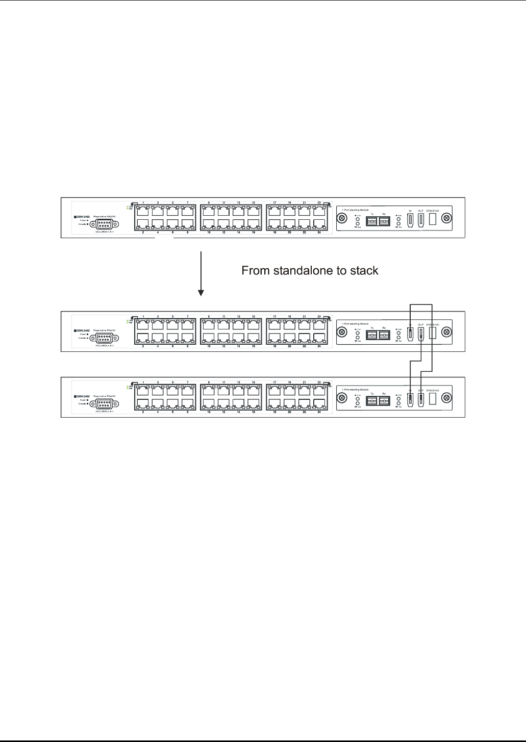
Power off both devices and place Switch B under Switch A in the rack. It is not actually required that the slave device be
placed under the master in the stack but it may be easier so that the master Switch may be instantly recognized. This may prove
especially convenient where multiple Switch stacks are installed so it is always clear which unit should be used to uplink.
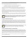
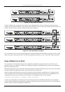
Figure 4- 3. Convert a Standalone Switch to a Stacked Switch
Both Switches are now powered off. Switch B is placed securely in the rack and connected to Switch A via the stacking ports.
Both devices are powered on; they recognize the stacking connection and begin negotiating the stacking relationship. Switch A
is configured to function as the master device. Switch B automatically assume slave status. Switch A will keep its IP settings
and its other configurations remain unchanged. The stack may now be configured as a single entity.
Add a Switch to a Stack
Adding a new slave device to a Switch stack is a simple procedure. If you are swapping an existing Switch, label each Ethernet
cable attached to the device being swapped so they can be placed in the same port number in the replacement device.
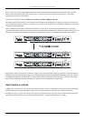
To add a new slave to a stack, place the new unit in the next available slot below the stack. Power off all Switches in the stack
and make the necessary changes to the stacking cable connections. Use the illustrations below as a guide.
14