


Stackable NWay Ethernet Switch User’s Guide
Identifying External Components 17
3
3 I
DENTIFYING
E
XTERNAL
C
OMPONENTS
This chapter describes the front panel, rear panel, optional plug-in modules, and LED indicators of the Switch
Front Panel
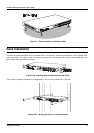
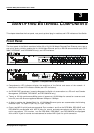
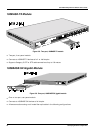
The front panel of the Switch consists of either 22 or 20 (10/100 Mbps) Ethernet/Fast Ethernet ports, two or
one uplink jacks, a slide-in module slot for 10/100 Mbps Ethernet ports, an RS-232 communication port (DES-
3624i, DES-3624iF, and DES-3624iFM only), and LED indicators.
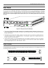
Figure 3-1. Front panel view of the Switches
♦
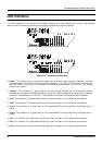
Comprehensive LED indicators display the conditions of the Switch and status of the network. A
description of these LED indicators follows (see
LED Indicators
).
♦
An RS-232 DCE console port is used to diagnose the Switch via a connection to a PC and Local Console
Management (DES-3624i, DES-3624iF, and DES-3624iFM only).
♦
Twenty or 22 high performance NWay ports all operate at 10/100 Mbps for connection to servers and
hubs. All ports can be auto-negotiated between 10Mbps or 100Mbps.
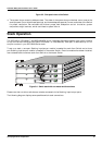
♦
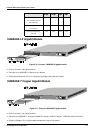
A slide-in module slot (labeled Slot1) for 10/100 Mbps Ethernet ports can accommodate the following
modules: 2-port TX, 2-port FX (MT-RJ), or 1-port FX (SC).
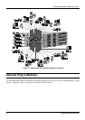
♦
One or two MDI-
II
uplink jacks are supported. Port numbers 1 and 2 on the DES-3624, DES-3624F, and
DES-3624FM are equipped with MDI-
X
jacks for normal end-node connections and MDI-
II
jacks for
uplink connections. Port number 1 on the DES-3624i, DES-3624iF, and DES-3624iFM are equipped
with an MDI-
X
jack for normal end-node connection and an MDI-
II
jack for uplink connection.