


Stackable NWay Ethernet Switch User’s Guide
36 Switch Management Concepts
IEEE 802.1Q VLANs
The Switch supports up to 96 IEEE 802.1Q (port-based) VLANs. Port-based VLANs limit traffic that flows
into and out of switch ports. Thus, all devices connected to a port are members of the VLAN(s) the port
belongs to, whether there is a single computer directly connected to a switch, or an entire department.
On port-based VLANs, NICs do not need to be able to identify 802.1Q tags in packet headers. NICs send and
receive normal Ethernet packets. If the packet’s destination lies on the same segment, communications take
place using normal Ethernet protocols. Even though this is always the case, when the destination for a packet
lies on another switch port, VLAN considerations come into play to decide if the packet gets dropped by the
switch or delivered.
There are two key components to understanding IEEE 802.1Q VLANs; Port VLAN ID numbers (PVID) and
VLAN ID numbers (VID). Both variables are assigned to a switch port, but there are important differences
between them. A user can only assign one PVID to each switch port. The PVID defines which VLAN a switch
will forward packets from the connected segment on, when packets need to be forwarded to another switch
port or somewhere else on the network. On the other hand, a user can define a port as a member of multiple
VLANs (VIDs), allowing the segment connected to it to receive packets from many VLANs on the network.
These two variables control a port’s ability to transmit and receive VLAN traffic, and the difference between
them provides network segmentation, while still allowing resources to be shared across more than one VLAN.
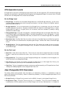
VLAN Segmentation
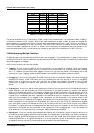
Take for example a packet that is transmitted by a machine on Port 1 that is a member of VLAN 2 and has
the Port VLAN ID number 2 (PVID=2). If the destination lies on another port (found through a normal
forwarding table lookup), the switch then looks to see if the other port (Port 10) is a member of VLAN 2 (and
can therefore receive VLAN 2 packets). If port 10 is not a member of VLAN 2, then the packet will be dropped
by the switch and will not reach it’s destination. If Port 10 is a member of VLAN 2, the packet will go through.
This selective forwarding feature based on VLAN criteria is how VLANs segment networks. The key point
being that Port 1 will only transmit on VLAN 2, because it’s Port VLAN ID number is 2 (PVID=2).
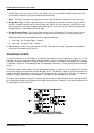
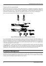
Sharing Resources Across VLANs
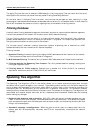
Network resources such as printers and servers however, can be shared across VLANs. This is achieved by
setting up overlapping VLANs as shown in the diagram below.
VLAN 1
Port
VIDs = 1
VLAN 2
Port
VIDs = 2
Port
PVID = 3
V
L
A
N
3
12
3
4
56
7
8910
11 12
Graphics
Workstations
Workstations
Network
S
e
rv
e
r
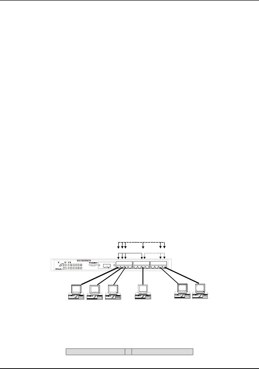
Figure 5-4. Example of typical VLAN configuration
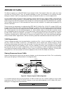
In the above example, there are three different VLANs and each port can transmit packets on one of them
according to their Port VLAN ID (PVID). However, a port can receive packets on all VLANs (VID) that it
belongs to. The assignments are as follows:
Transmit on VLAN # Member of VLAN #