


Stackable NWay Ethernet Switch User’s Guide
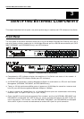
24 Identifying External Components
LED Indicators
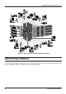
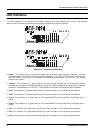
The LED indicators of the Switch include Power, Console, Slot, Giga, Speed, and Link/Act. The following
shows the LED indicators for the Switch along with an explanation of each indicator.
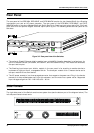
Figure 3-12. The Switch LED indicators
♦
Power
This indicator on the front panel should light green after approximately 2 seconds to indicate
the ready state of the Switch when the device is powered on. The LED will blink when the Power-On
Self-Test (POST) is running or if the system’s configuration has changed. This LED will light orange
when an error occurs.
♦
Console
This indicator is lit green when the switch is being managed via out-of-band/local console
management through the RS-232 console port using a straight-through serial cable. When a secured
connection is established, this LED is lit. The indicator blinks when the console RS-232 is accessed.
♦
Slot2
This indicator is lit green when a slide-in module is present in the rear panel of the Switch.
♦
Slot3
This indicator is lit green when a slide-in module is present in the rear panel of the Switch.
♦
Giga1
This indicator is lit green when a link is established. It blinks green when the Gigabit port is
active.
♦
Giga2
This indicator is lit green when a link is established. It blinks green when the Gigabit port is
active.
♦
Sio1
This indicator is lit green when a Stacking IO port is present in the rear panel of the Switch.
♦
Sio2
This indicator is lit green when a Stacking IO port is present in the rear panel of the Switch.
♦
Sio3
This indicator is lit green when a Stacking IO port is present in the rear panel of the Switch.