


Stackable NWay Ethernet Switch User’s Guide
18 Identifying External Components
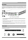
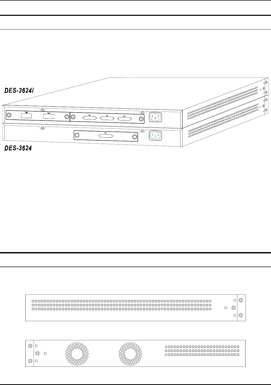
Rear Panel
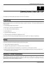
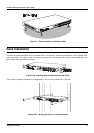
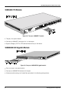
The rear panel of the DES-3624, DES-3624F, and DES-3624FM consist of a slot (labeled Slot2) for a Stacking
input/output port and an AC power connector. The rear panel of the DES-3624i, DES-3624iF, and DES-
3624iFM consist of two slots (labeled Slot2 and Slot3). Slot2 is for Stacking input/output ports Sio1, Sio2, and
Sio3. Slot3 is for an optional Gigabit Ethernet uplink (MDI-
II
) port. The following shows the rear panel of the
Switches.
Figure 3-2. Rear panel view of the Switches
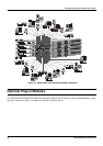
♦
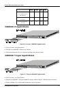
The optional Gigabit Ethernet slide-in module is an uplink/MDI-
II
(media dependent interface) port for
uplink to another Switch (DES-3624i, DES-3624iF, and DES-3624iFM only). Two models are available,
one-port and two-port.
♦
The Stacking input/output port slide-in module in the rear panel is for stacking to another device to
implement a high-port count, manageable Switch. The three-port module is for a master device and a
one-port module is for a client device.
♦
The AC power connector is a three-pronged connector that supports the power cord. Plug in the female
connector of the provided power cord into this connector, and the male into a power outlet. Supported
input voltages range from 100 ~ 240 VAC at 50 ~ 60 Hz.
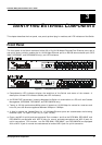
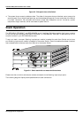
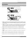
Side Panels
The right side panel of the Switch contains two system fans (see the bottom part of the diagram below). The
left side panel contains heat vents.