


14 ProLink
®
II Software for Micro Motion
®
Transmitters
Installation and Setup
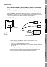
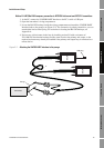
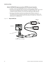
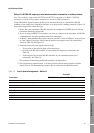
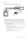
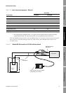
3. If necessary, add a resistor to the connection as required by your transmitter (see Table 2-7).
- If no other device is connected to the primary mA output, add the resistor in parallel with
the primary mA output.
- If the primary mA output is connected to a remote device such as a DCS or a PLC with an
internal resistor (R2), ensure its value is within the range described in Table 2-7. If it is
lower than 250 Ω, add resistor R1 to the connection so that the overall resistance (R1 + R2)
is within the range described in Table 2-7.
- If your DCS or PLC does not have an internal resistor, add resistor R3 and make sure its
value is within the range described in Table 2-7
.
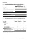
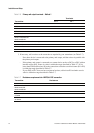
Table 2-6 Primary mA output terminals – Method 1
Transmitter
Terminals
PV + PV –
RFT9712 17 16
RFT9739 rack-mount Z30 D30
RFT9739 field-mount 17 18
IFT9701/9703 4–20 mA 4–20 mA
Model 1500/2500 21 22
Model 1700/2700 AN
Model 1700/2700 CIO
Model 2400S AN
12
Series 3000 panel-mount with screw-type connectors c2 a2
Series 3000 panel-mount with I/O cables 14 15
Series 3000 rack-mount c2 a2
Series 3000 field-mount 2 1
Table 2-7 Resistance requirements for HART/Bell 202 connection
Transmitter Resistance
Model 1500/2500 250–600 Ω
Model 1700/2700 AN
Model 2700 CIO
Model 2400S AN
250–600 Ω
Series 3000 (all models) 250–600 Ω
IFT9701
IFT9703
250–600 Ω
RFT9712
RFT9739
250–1000 Ω