


64 ProLink
®
II Software for Micro Motion
®
Transmitters
Transmitter Configuration, Characterization, and Calibration
5.6 Compensating for pressure
Some Micro Motion transmitters can compensate for the effect of pressure on the sensor flow tubes.
Pressure effect is defined as the change in sensor flow and density sensitivity due to process pressure
change away from calibration pressure.
5.6.1 Options
There are two ways to compensate for pressure:
• If the pressure is a known static value, you may choose to enter the external pressure in the
software and not poll a pressure measurement device.
• If the operating pressure varies significantly, you may choose to have the transmitter poll for
an updated pressure value from an external pressure measurement device. Polling requires
HART protocol.
Note: If you poll for pressure, ensure that the external pressure measurement device is accurate and
reliable.
5.6.2 Pressure correction factors
When configuring pressure compensation, you must provide the flow calibration pressure – the
pressure at which the meter was calibrated (which therefore defines the pressure at which there will be
no effect on the calibration factor). Enter 20 PSIG unless the calibration document for your sensor
indicates a different calibration pressure.
Two additional pressure correction factors may be configured: one for flow and one for density. These
are defined as follows:
• Flow factor – the percent change in the flow rate per psi
• Density factor – the change in fluid density, in g/cm
3
/psi
Not all sensors or applications require pressure correction factors. For the values to be used, obtain the
pressure effect values from the product data sheet for your sensor, then reverse the signs (e.g., if the
pressure effect is 0.000004, enter a pressure correction factor of –0.000004). For more information,
contact Micro Motion customer service.
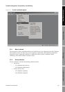
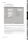
5.6.3 Configuration
To enable and configure pressure compensation:
1. From the
View menu, select Preferences and ensure that the Enable External Pressure
Compensation
checkbox is checked.
2. Open the
Configuration panel and click the Pressure tab.
3. Enter new values in the
Flow factor, Density factor, and Cal Pressure boxes. See the
discussion in the previous section.
4. If you will poll an external device for pressure data:
a. If your transmitter is a model RFT9739, RFT9712 or IFT9701/03, set
Pressure units to
the unit used by the external pressure measurement device.
b. Click
Apply.
c. Follow the polling setup instructions in Section 5.8.