


Installation and Use Manual 57
Transmitter Configuration, Characterization, and Calibration
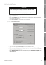
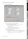
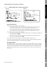
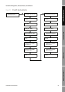
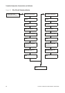
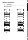
Meter Verification Transmitter TerminalsData LoggerTransmitter Configuration
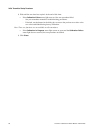
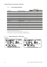
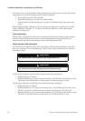
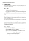
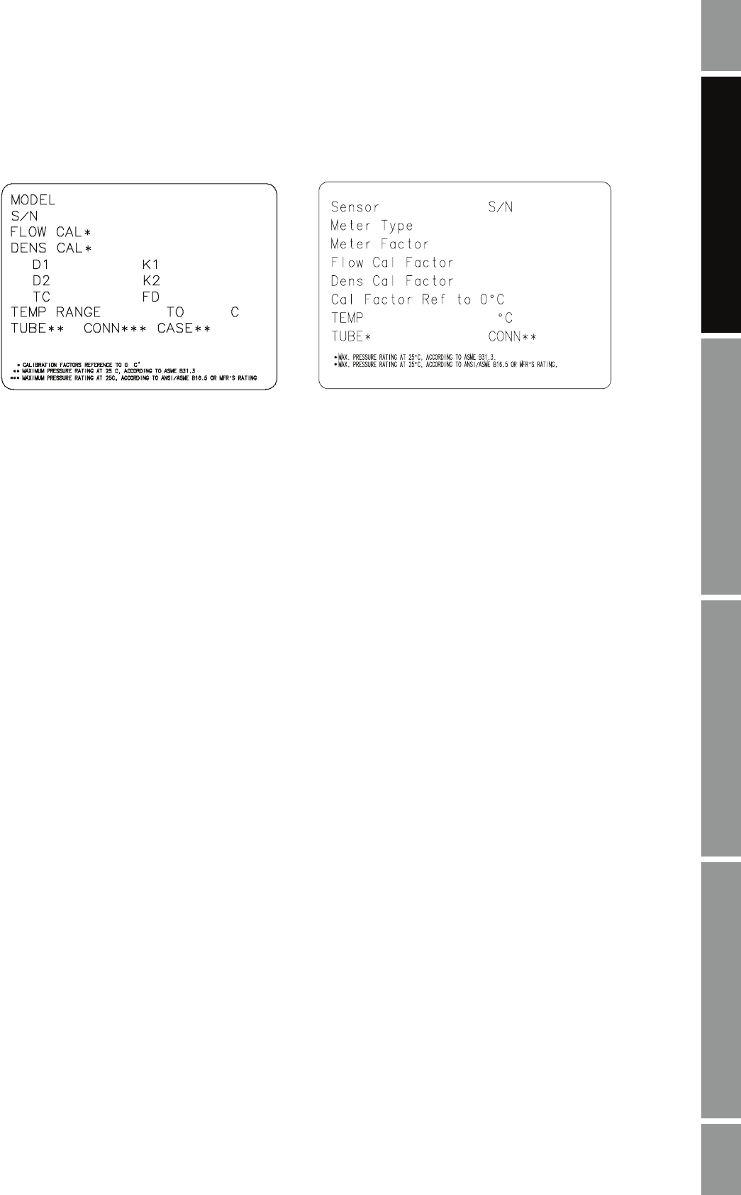
Figure 5-3 Sample calibration tags – All sensors except T-Series
Density calibration factors
If your sensor tag does not show a D1 or D2 value:
• For D1, enter the Dens A or D1 value from the calibration certificate. This value is the
line-condition density of the low-density calibration fluid. Micro Motion uses air.
• For D2, enter the Dens B or D2 value from the calibration certificate. This value is the
line-condition density of the high-density calibration fluid. Micro Motion uses water.
If your sensor tag does not show a K1 or K2 value:
• For K1, enter the first 5 digits of the density calibration factor. In the sample tag in Figure 5-3,
this value is shown as
12500.
• For K2, enter the second 5 digits of the density calibration factor. In the sample tag in
Figure 5-3, this value is shown as
14286.
If your sensor does not show an FD value, contact Micro Motion customer service.
If your sensor tag does not show a DT or TC value, enter the last 3 digits of the density calibration
factor. In the sample tag in Figure 5-3, this value is shown as
4.44.
Flow calibration values
Two separate values are used to describe flow calibration: a 6-character FCF value and a 4-character
FT value. Both values contain decimal points. During characterization, these are entered as a single
10-character string that includes two decimal points. In ProLink II, this value is called the Flowcal
parameter. In the Communicator, this value is called the FCF for T-Series sensors and Flowcal for
other sensors.
Newer tag Older tag
19.0005.13
19.0005.13
0.0010
0.9980
12502.000
14282.000
4.44000
310
12500142864.44
12500142864.44