Installation and Use Manual 25
Installation and Setup
ProLink II Setup Transmitter StartupUsing ProLink IIBefore You Begin
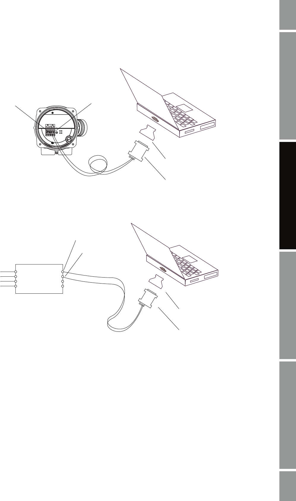
Figure 2-11 Modbus/RS-485 connection to RS-485 terminals on enhanced core processor
Figure 2-12 Modbus/RS-485 connection to RS-485 terminals on I.S. barrier
Core processor
RS-485 to RS-232
signal converter
25 to 9 pin serial port
adapter (if necessary)
RS-485/B
RS-485/A
RS-485 to RS-232
signal converter
25 to 9 pin serial port
adapter (if necessary)
RS-485/B
RS-485/A
I.S. barrier
Non-I.S. terminals


