


Installation and Use Manual 83
Transmitter Terminal Reference
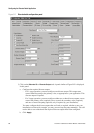
Meter Verification Transmitter TerminalsData LoggerTransmitter Configuration
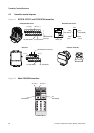
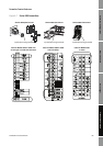
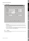
Figure A-3 Model 1700/2700 transmitters
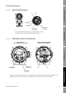
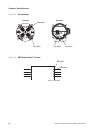
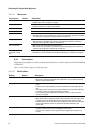
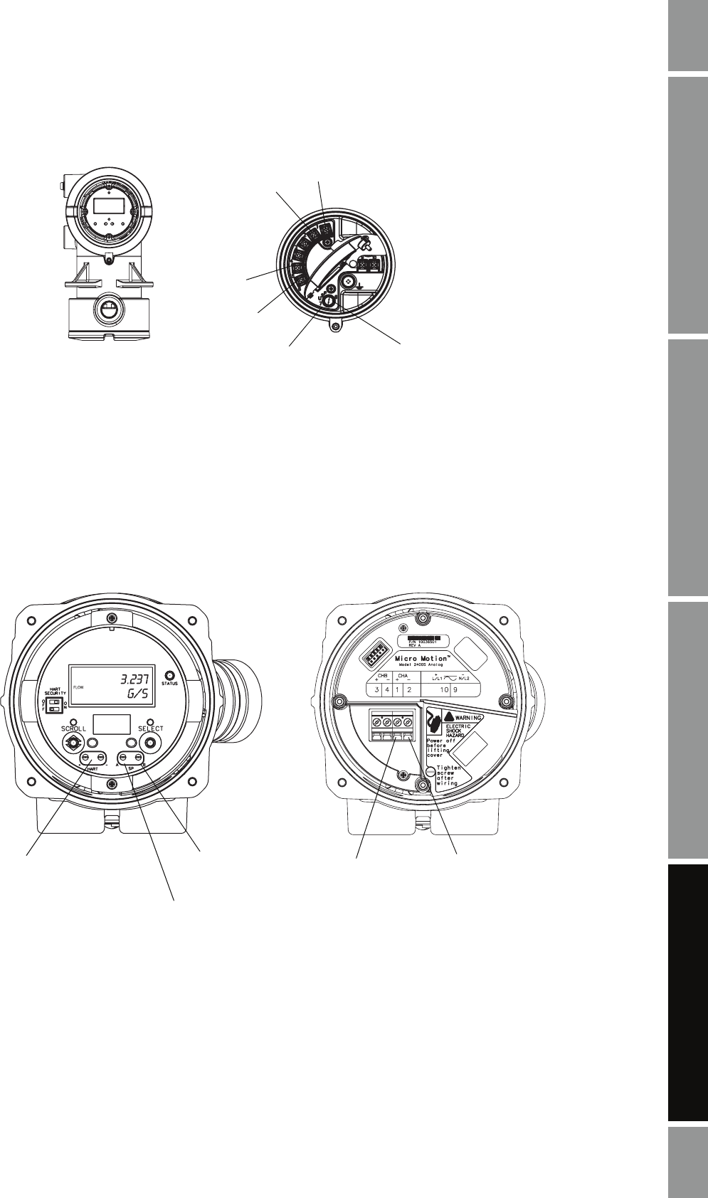
Figure A-4 Model 2400S transmitters with analog outputs
1 (+)
2 (–)
5
(RS-485/A)
6
(RS-485/B)
8
Service port
(RS-485/A)
7
Service port
(RS-485/B)
Note: Terminals 5 and 6 used for communications only by
transmitters with the analog outputs option board.
User interface
(with display, cover removed)
Outputs wiring compartment
(user interface removed)
HART clips
HART clips
1 (+)
2 (–)
Service port
(RS-485/B)
Service port
(RS-485/A)
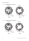
Note: The user interface shown here is equipped with a display. On models without a display, the
HART clips and service port clips are located in the same position on the user interface.