


Installation and Use Manual 21
Installation and Setup
ProLink II Setup Transmitter StartupUsing ProLink IIBefore You Begin
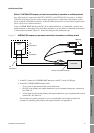
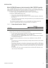
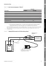
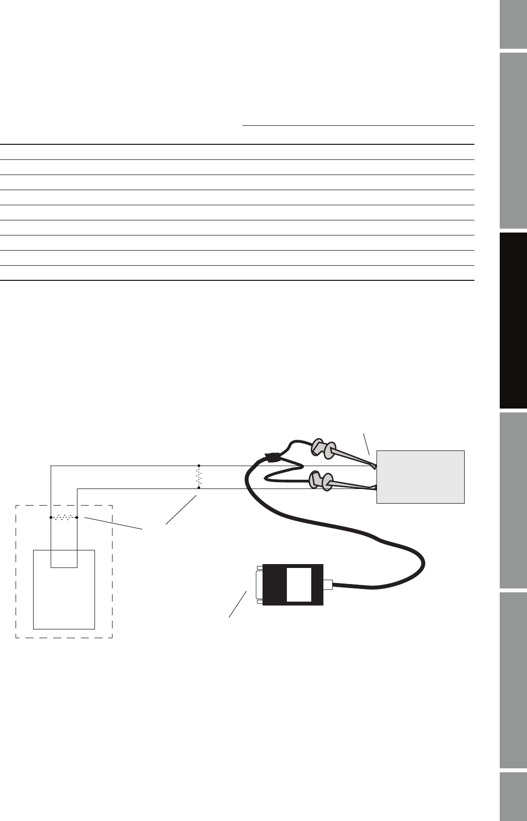
3. For long-distance communication, or if noise from an external source interferes with the
signal, install 120-Ω, 1/2-watt resistors (R1) across terminals of both end devices.
Note: The Modbus protocol allows only one Modbus master to be active on the network at any given
time. If you are connecting through a network, ensure that no other Modbus master devices are
currently active.
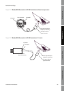
Figure 2-7 Modbus/RS-485 connection to RS-485 multidrop network
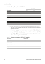
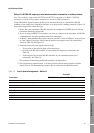
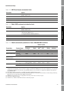
Table 2-10 Lead-to-terminal assignments – Method 6
Transmitter
Terminals
RS-485/A RS-485/B
Model 1500/2500 33 34
Model 1700/2700 AN 5 6
Series 3000 panel-mount with screw-type connectors a32 c32
Series 3000 panel-mount with I/O cables 25 24
Series 3000 rack-mount a32 c32
Series 3000 field-mount 12 11
RFT9712 21 22
RFT9739 field-mount 27 26
RFT9739 rack-mount Z22 D22
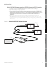
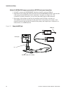
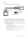
DCS or
PLC
R1
See Step 3
BLACK
BOX
25-pin to 9-pin serial port adapter
(if necessary) (not shown)
RS-485 terminals
See Step 2
Trans mit ter