ROC827 Instruction Manual
Issued Mar-06 Communications 5-11
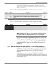
EIA-422/485 (RS-422/485) communication modules include LED
indicators that display the status of receive and transmit activity. Refer to
Tables 5-9 and 5-10.
Table 5-9. EIA-422 (RS-422) Signal Routing – Comm3, Comm4, and Comm5
Signal RS-422 Function Terminal
A RX + Lit when module (Comm3, Comm4, or Comm5) is currently receiving. 1
B RX – None. 2
Y TX + Lit when module (Comm3, Comm4, or Comm5) is currently transmitting. 3
Z TX – None. 4
COM Common Ground. 5
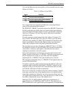
Table 5-10. EIA-485 (RS-485) Signal Routing – Comm3, Comm4, and Comm5
Signal RS-485 Function Terminal
A RX / TX + Lit when module (Comm3, Comm4, or Comm5) is currently receiving. 1
B RX / TX – Lit when module (Comm3, Comm4, or Comm5) is currently transmitting. 2
Y No Connect None. 3
Z No Connect None. 4
COM Common Ground. 5
Note: The EIA-422/485 (RS-422/485) modules are isolated on the field
side. Be aware that you can induce ground loops by tying commons
together.
EIA-422/485 (RS-422/485) communications provides EIA-422/485 (RS-
422/485) signals on the Comm3, Comm4, or Comm5 port, depending on
where the module is installed. Wiring should be twisted-pair cable, one
pair for transmitting, and one pair for receiving. The EIA-422 (RS-422)
module uses four wires and the EIA-485 (RS-485) uses two wires for
connectivity.
5.8.1 EIA-422/485 (RS-422/485) Jumpers & Termination Resistors
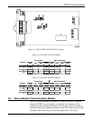
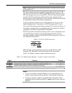
Four jumpers—J3, J4, J5, and J6—are located on the EIA-422/485 (RS-
422/485) communications module. These jumpers determine the mode in
which the module runs (RS-422 or RS-485) and if the module is
terminated.
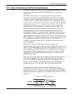
Terminations are required on the two EIA-422/485 (RS-422/485)
communication modules located at the extremities of the circuit. That is to
say, the two outside modules require terminations in order to complete the
communications circuit.


