


ROC827 Instruction Manual
Issued Mar-06 Communications 5-15
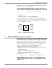
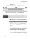
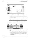
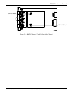
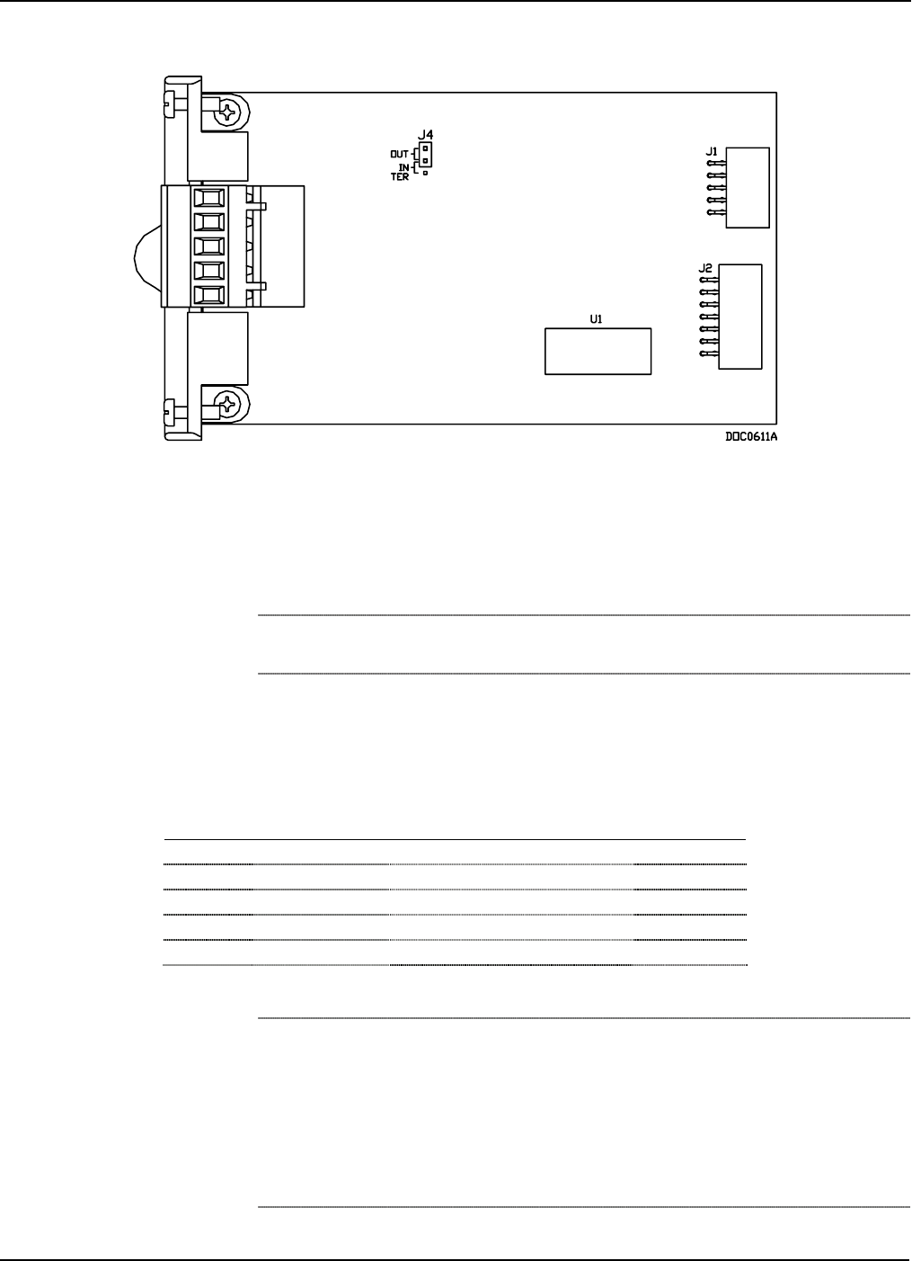
Figure 5-6. MVS Jumper J4 (Shown Not Terminated)
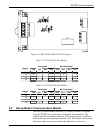
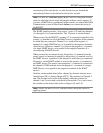
Four wires run from the MVS module terminal block and connect to the
sensor. The wires should be a minimum size of 22 AWG and a maximum
length of 1220 m (4000 ft).
Note: Insulated, shielded, twisted-pair wiring is required when using MVS
signal lines.
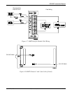
Two of the terminal blocks provide power and the other two terminals
provide a communication path. Table 5-16 identifies the terminals.
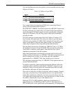
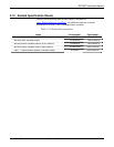
Table 5-16. MVS Signal Routing – Comm3, Comm4, and Comm5
Label MVS LED Terminal
A RX / TX + Lit green when receiving 1
B RX / TX – N/A 2
None No Connect Lit green when transmitting 3
+ Sensor Power N/A 4
– Common N/A 5
Notes:
Pay close attention to the connections; do not reverse the power
wires. Make these connections only after removing power from the
ROC827. Double-check connections for the proper orientation before
applying power. If the connections are reversed and power is applied,
you will damage both the MVS module and the ROC800-Series
processor board.