


ROC827 Instruction Manual
Issued Mar-06 Input/Output Modules 4-7
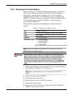
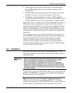
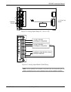
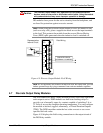
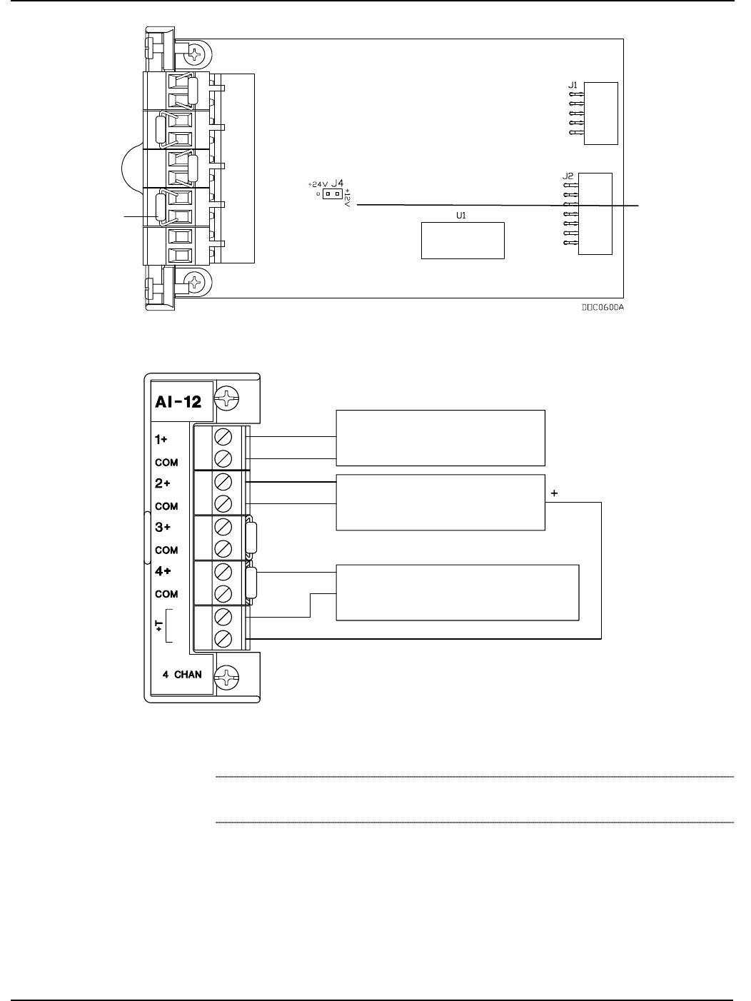
Figure 4-4. Analog Input Jumper J4 – Set to +24V
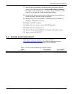
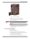
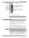
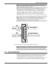
1-5 VOLT DEVICE
EXTERNALLY POWERED
+
-
1-5 VOLT DEVICE
EXTERNALLY POWERED
+
-
ROC809 POWERED
CURRENT LOOP DEVICE 4-20mA
-
+
OUT SIGNAL
COM IN
DOC0506A
Figure 4-5. Analog Input Module Field Wiring
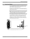
Note: All I/O modules are isolated on the field side. Be aware that you can
induce ground loops by tying commons from various modules together.
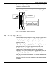
Precision
Resisto
r
+T 12 / 24 V dc
Jumper