


ROC827 Instruction Manual
Issued Mar-06 Power Connections 3-7
3.2 Determining Power Consumption
Determining the power consumption requirements for a ROC827
configuration involves the following steps:
1. Determine your ideal ROC827 configuration, which includes
identifying all modules, device relays, meters, solenoids, radios,
transmitters, and other devices that may receive DC power from the
complete ROC827 configuration (base unit and EXPs).
Note: You should also identify any devices (such as a touch screen
panel) that may be powered by the same system but not necessarily by
the ROC827.
2. Calculate the “worst-case” DC power consumption for that
configuration by totaling the combined power draw required for all
installed modules, as well as accounting for the power any modules
provide to external devices (through the use of +T).
Note: “+T” describes the isolated power some modules (such as AI,
AO, PI, and HART) may supply to external devices, such as 4–20 mA
pressure and temperature transducers.
3. Verify that the power input module you intend to use can meet the
power requirements calculated in the first step.
This verification helps you identify and anticipate power demands
from +T external devices that exceed the capabilities of the PM-12 or
PM-24 Power Input modules. In this case, you can then make
arrangements to externally power these field devices.
4. “Tune” (if necessary) the configuration by providing external power
or re-assessing the configuration to lessen the power requirements
from the ROC827.
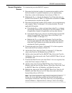
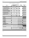
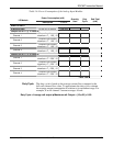
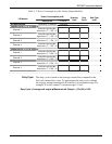
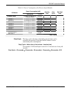
To assist you in this process, this chapter contains a series of worksheets
(Tables 3-5 through 3-16) that help you to identify and assess the power
requirements for each component of your ROC827 system. Table 3-5
identifies the power requirements related to the ROC827 base unit and
summarizes the power requirements you identify on Tables 3-6 through
3-16. (Complete Tables 3-6 through 3-15 to calculate the power
consumption for each of the I/O modules, and then transfer those results
to Table 3-5.) Completing Table 3-5 enables you to quickly determine
whether the power input module you intend to use is sufficient for your
configuration. If the power module is not sufficient, you can then review
individual worksheets to determine how to best “tune” your configuration
and lessen power demands.