ROC827 Instruction Manual
Issued Mar-06 Input/Output Modules 4-6
6. Replace the wire channel cover.
4.2.3 Wiring I/O Modules
All modules have removable terminal blocks for convenient wiring and
servicing. The terminal blocks can accommodate a wide range of wire
gauges (12 AWG or smaller).
Caution
Failure to exercise proper electrostatic discharge precautions, such as
wearing a grounded wrist strap may reset the processor or damage
electronic components, resulting in interrupted operations.
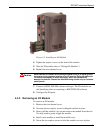
To connect the wire to the removable block compression terminals:
1. Bare the end (¼ inch maximum) of the wire.
2. Insert the bared end into the clamp beneath the termination screw.
3. Tighten the screw.
The ROC827 should have a minimum of bare wire exposed to prevent
short circuits. Allow some slack when making connections to prevent
strain.
Note: All modules have removable terminal blocks for convenient wiring
and servicing. Twisted-pair cable is recommended for I/O signal wiring.
The removable terminal blocks accept 12 AWG or smaller wire.
4.3 Analog Input Modules
The four Analog Input (AI) channels are scalable, but typically measure
either:
4- to 20-mA analog signal, with the use of a precision resistor
(supplied).
1 to 5 Volts dc signal.
If required, you can calibrate the low end of the analog signal to zero.
You can configure the AI (+T) module as either 12 or 24 Volt dc using
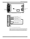
jumper J4 on the I/O module (see Figure 4-4). The AI modules can
provide isolated +12 Volt dc or +24 Volt dc field transmitter power on a
per-module basis. For example, one module can provide +12 Volts dc for
powering low power analog transmitters, while another module in the
same ROC827 can provide +24 Volts dc for powering conventional 4- to
20-mA transmitters. Refer to Figure 4-5:


