ROC827 Instruction Manual
Issued Mar-06 Installation and Use 2-13
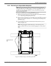
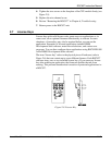
4. Using a flat-bladed screwdriver, gently pry the plastic locking clips at
the upper and lower back edge of the EXP housing away from their
securing tabs.
Note: Applying too much pressure breaks the plastic hooks.
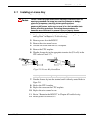
5. Once you free the plastic locking clips from their securing tabs, gently
pivot the back of the EXP away from the ROC827.
Note: The EXP detaches quickly. Hold it securely to prevent it from
falling.
6. Place the detached EXP in a secure location.
7. Replace the right-hand end cap.
8. Replace the ROC827 on the DIN rail.
9. Reattach all wiring.
10. Replace the wire channel covers.
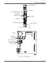
2.6 Central Processor Unit (CPU)
The ROC827 uses a standard ROC800-Series central processing unit
(CPU) containing the microprocessor, the firmware, connectors to the
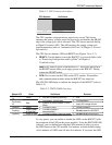
backplane, the three built-in communication ports (two with LEDs), a
LED low power wakeup button, a RESET button, the application License
Key connectors, a STATUS LED indicating system integrity, and the main
processor (refer to Figures 2-5 and 2-6 and Tables 2-1 and 2-2).
The 32-bit microprocessor is based on a Motorola MPC862 Quad
Integrated Communications Controller (PowerQUICC) PowerPC
processor running at 50 MHz.
The internal Sanyo 3-volt CR2430 lithium backup battery provides backup
of the data and the Real-Time Clock when the main power is not
connected.


