ROC827 Instruction Manual
Issued Mar-06 Communications 5-5
6. Replace the wire channel cover.
5.4 Wiring Communications Modules
Signal wiring connections to the communications are made through the
communications port removable terminal bock connectors and through RJ-
11 and RJ-45 connectors. All modules have removable terminal blocks for
convenient wiring and servicing. The terminal blocks can accommodate a
wide range of wire gauges (12 AWG or smaller).
Caution
Failure to exercise proper electrostatic discharge precautions, such as
wearing a grounded wrist strap may reset the processor or damage
electronic components, resulting in interrupted operations.
To connect the wire to the removable block compression terminals:
1. Bare the end (¼ inch maximum) of the wire.
2. Insert the bared end into the clamp beneath the termination screw.
3. Tighten the screw.
The ROC827 should have a minimum of bare wire exposed to prevent
short circuits. Allow some slack when making connections to prevent
strain.
Note: All modules have removable terminal blocks for convenient wiring
and servicing. Twisted-pair cable is recommended for I/O signal wiring.
The removable terminal blocks accept 12 AWG or smaller wire.
5.5 Local Operator Interface (LOI)
The Local Operator Interface (LOI) local port provides direct
communications between the ROC827 and the serial port of an operator
interface device, such as an IBM compatible computer. The interface
allows you to access the ROC827 with a direct connection using
ROCLINK 800 software to configure and transfer stored data.
The LOI uses the Local Port in ROCLINK 800 software.
The LOI terminal (RJ-45) on the CPU provides wiring access to a built-in
EIA-232 (RS-232) serial interface, which is capable of 57.6K baud
operation. The RJ-45 connector pin uses the data terminal equipment
(DTE) in the IEEE standard.
The LOI port supports ROC Plus and Modbus protocol communications.
The LOI also supports the log-on security feature of the ROC827 if you
have enabled the Security on LOI in the ROCLINK 800 software.
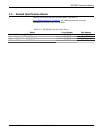
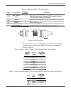
Table 5-3 shows the signal routing of the CPU connections. Figure 5-3
shows the RJ-45 pin out.


