ROC827 Instruction Manual
Issued Mar-06 Input/Output Modules 4-12
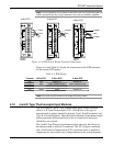
Note: The Discrete Output Relay module operates only with discrete
devices having their own power source.
When a request is made to change the state of a DOR, the request is
immediately sent to the DOR module. There is no scan time associated
with a DOR. Under normal operating conditions, the DOR channel
registers the change within 12 mSecs. If the DOR is in momentary or
toggle mode, DOR channels register the change within 48 mSecs.
The DOR modules draw power for the active circuitry from the backplane.
Note: On power up or reset, the DO Relay module’s LEDs enter
indeterminate state for a few seconds as the module self-identifies. The
LEDs may flash, stay on, or stay off for a few seconds.
CONTROL
V
s
CONTROL
V
s
EXTERNALLY POWERED
DISCRETE DEVICE
+
-
-
+
SELF- POWERED
DISCRETE DEVICE
-
+
+
-
-
-
-
+
+
+
-
C
H
1
C
H
2
C
H
3
C
H
4
C
H
5
-
Y
DO
RELA
5 CHAN
DOC0509A
RS
RS
LATCHING RELAY
NOTE: S = SET
R = RESET
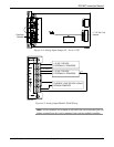
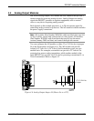
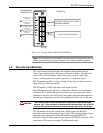
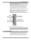
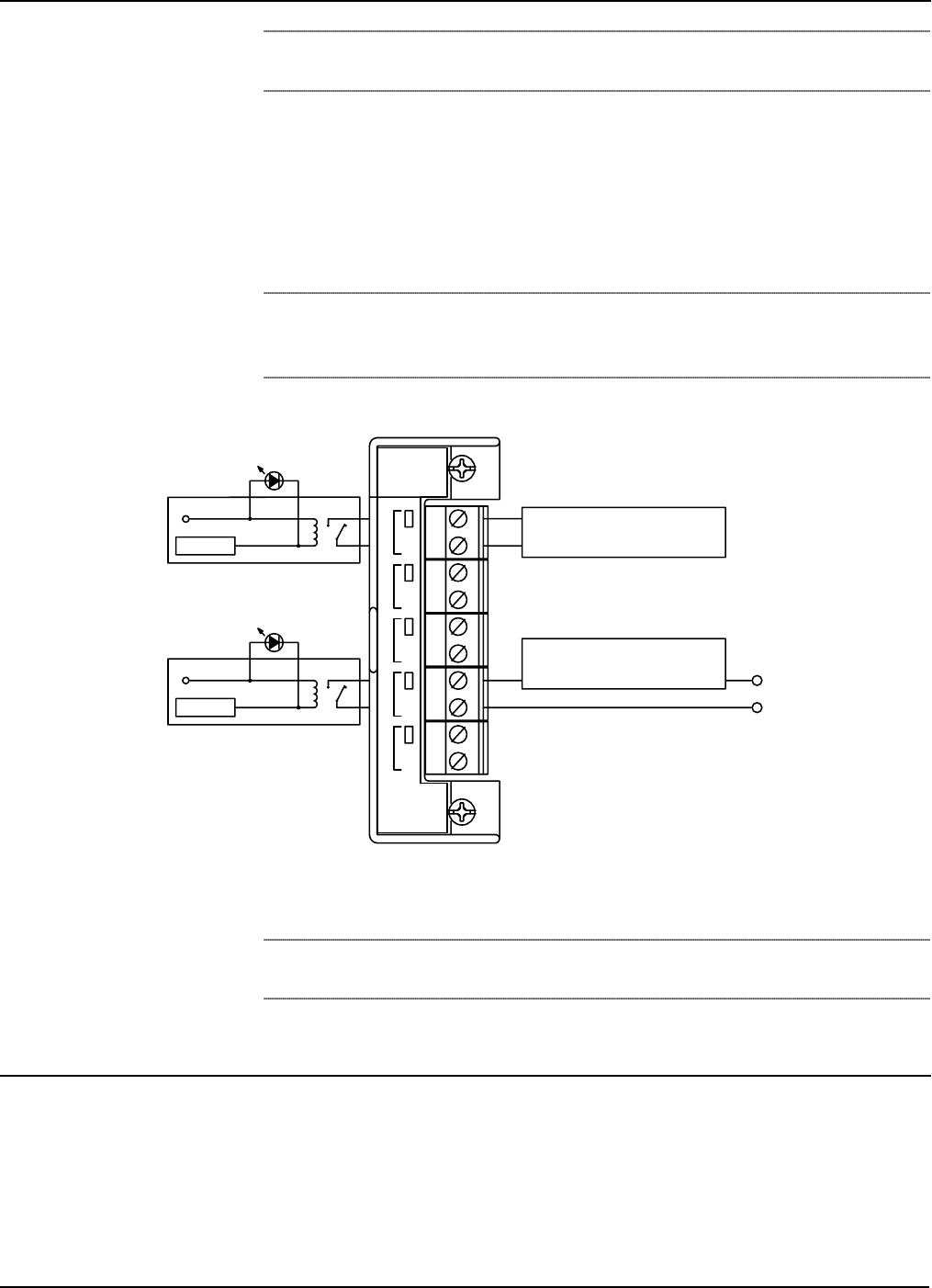
Figure 4-10. Discrete Output Relay Module Field Wiring
Note: All I/O modules are isolated on the field side. Be aware that you can
induce ground loops by tying commons from various modules together.
4.8 Pulse Input Modules
The Pulse Input (PI) module provides two channels for measuring either a
low speed or high speed pulse signal. The PI module processes signals
from pulse-generating devices and provides a calculated rate or an
accumulated total over a configured period. Supported functions are slow-
counter input, slow rate input, fast counter input, and fast rate input.


