ROC827 Instruction Manual
Issued Mar-06 Communications 5-13
Note: When installing a dial-up modem module, you must remove power
from the ROC827.
The dial-up modem provides communications with speeds up to 14.4K
bps with V.42 bis and V.42, MNP2-4 and MNP10 error correction, and is
FCC Part 68 approved for use with PSTNs. The FCC label on the module
provides the FCC registration number and the ringer equivalent. The
module supports data compression, error correction, and nonvolatile RAM
for permanent storage of the modem configuration.
Using asynchronous operation, the module interfaces to two-wire, full-
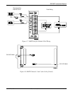
duplex telephone lines. It interfaces to a PSTN through an RJ-11 jack.
You control the modem using industry-standard AT command software. A
40-character command line is provided for the AT command set, which is
compatible with EIA document TR302.2/88-08006.
The dial-up modem automatically hangs up after a user-configured period
of communications inactivity and provides automated dial-up alarm
reporting capabilities. Refer to the ROCLINK 800 Configuration Software
User Manual (Form A6121).
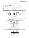
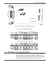
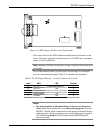
Table 5-13. RJ-11 Field Connections
Signal Pin
Tip 3
Ring 4
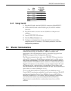
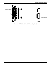
LED indicators on the module show the status of the Receive (RX),
Transmit (TX), Ring (RI), and Carrier Detect (CD) control lines.
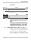
Table 5-14 displays connector signals and their functions.
Table 5-14. Modem Signal Routing – Comm3, Comm4, and Comm5
Signal Function Terminal
RX Lit when module (Comm3, Comm4, or Comm5) is currently receiving. 1
TX Lit when module (Comm3, Comm4, or Comm5) is currently transmitting (Tip). 3
RI Lit when module (Comm3, Comm4, or Comm5) on ring (Ring). 7
CD Lit when module (Comm3, Comm4, or Comm5) on carrier detect. 9
Notes:
If you are installing a modem module, it is recommended that you
install a surge protector between the RJ-11 jack and the outside line.
The dial-up modem is not hot-swappable or hot-pluggable. When
installing a dial-up modem module, you must remove power from the
ROC827.


