ROC827 Instruction Manual
Issued Mar-06 Input/Output Modules 4-10
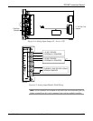
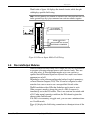
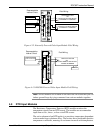
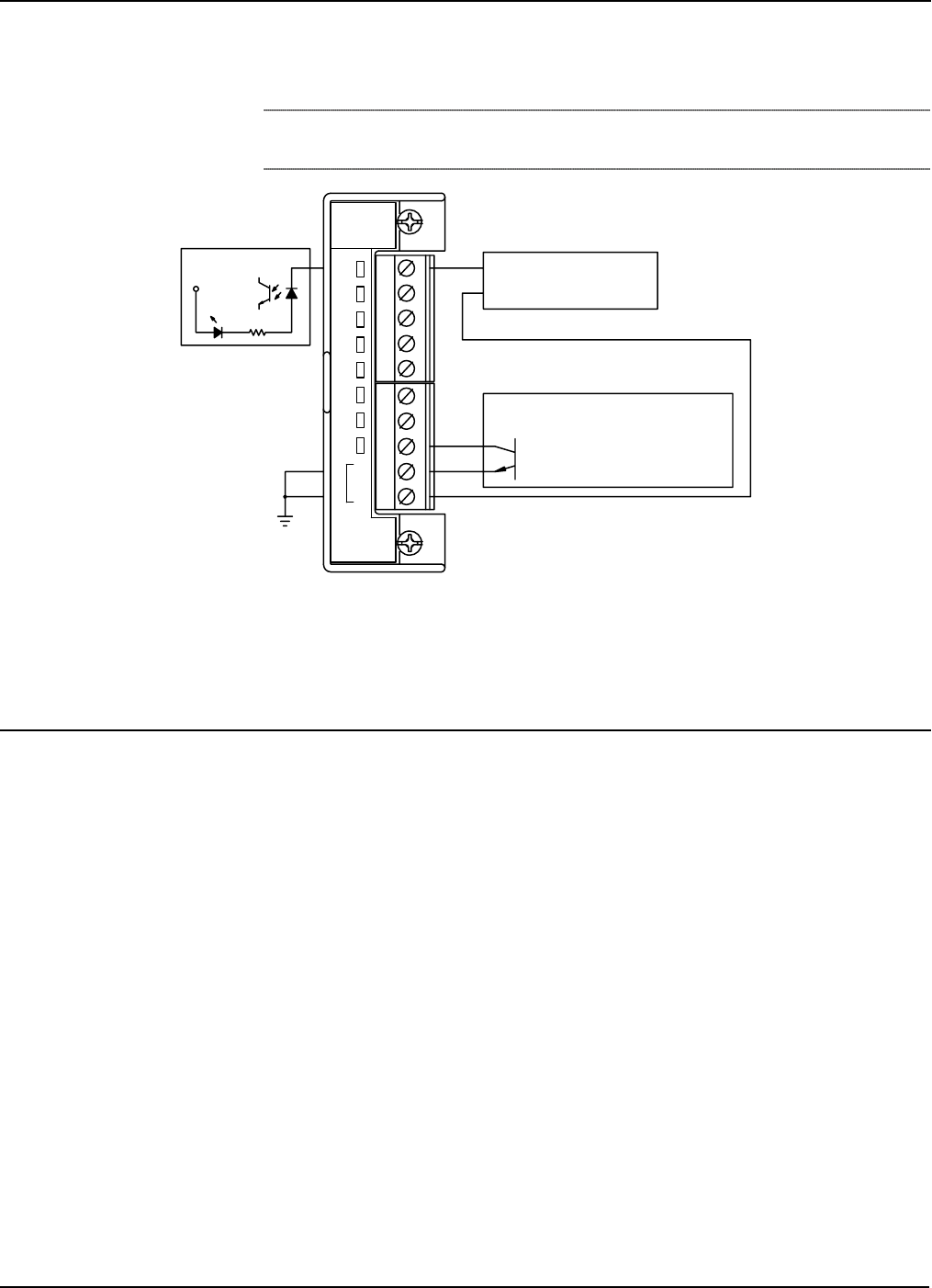
The left side of Figure 4-8 displays the internal circuitry while the right
side displays possible field wiring.
Note: All I/O modules are isolated on the field side. Be aware that you can
induce ground loops by tying commons from various modules together.
+
-
DRY CONTACT
ROC800 POWERED
+
-
+V
6.6KW
DOC0507A
C
O
M
6
8
7
4
5
3
2
1
DI
8 CHAN
OPEN DRAIN TYPE DEVICE
OR
OPEN COLLECTOR
EXTERNALLY POWERED
Figure 4-8. Discrete Input Module Field Wiring
4.6 Discrete Output Modules
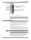
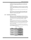
The five-channel Discrete Output (DO) module provides two-state outputs
to energize solid-state relays and power small electrical loads. These are
solid-state relays. A Discrete Output may be set to send a pulse to a
specified device. Discrete Outputs are high and low outputs used to turn
equipment on and off.
DO modules can be software-configured as latched, toggled, momentary,
or Timed Duration Outputs (TDO). The DO can be configured to either
retain the last value on reset or use a user-specified fail-safe value.
The DO module provides LEDs that light when each output is active.
When a request is made to change the state of a DO, the request is
immediately sent to the DO module. There is no scan time associated with
a DO. Under normal operating conditions, the DO channel registers the
change within 2 milliseconds.
If the DO is in momentary or toggle mode, you can enter a minimum time-
on of 4 milliseconds.
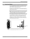
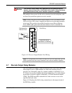
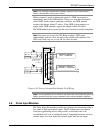
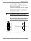
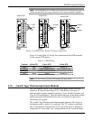
Figure 4-9 displays the field wiring connections to the output circuit of the
DO module.


