ROC827 Instruction Manual
Issued Mar-06 Communications 5-17
second per poll for each device, so with five devices per channel the
maximum poll time for the channel would be five seconds.
Note: The ROC827 does not support HART devices configured in Burst
mode (in which the device sends information without a prior request). If
you have a HART device configured in Burst mode, use a hand-held Field
Communicator to turn off Burst mode before you connect the device to
the ROC827.
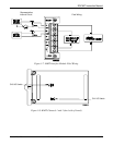
The HART module provides “loop source” power (+T) and four channels
(1+ through 4+) for communications. The +T power is current-limited.
When powered by the ROC827, terminal +T is connected in parallel to the
positive (+) terminal on all of the HART devices, regardless of the channel
to which they are connected. Channel 1+ is wired to the negative (–)
terminal of a single HART device, or in parallel to the negative terminals
of the devices. Likewise, channel 2+ is wired to the negative (–) terminal
of a single HART device, or in parallel to the negative terminals of a
second group of HART devices.
When powered by an external device, the positive (+) terminal from the
power source is connected in parallel to the positive (+) terminal on all of
the HART devices, regardless of the channel to which they are connected.
Channel 1+ on the HART module is wired to the positive (+) terminal of
the HART device. The power source negative (–) terminal is connected to
the channel’s COM terminal and to the negative (–) terminal of a single
HART device, or in parallel to the negative terminals of the HART
devices.
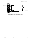
Switches on the module board allow channel-by-channel selection as an
Analog Input (IN) or Analog Output (OUT). The switches for Channel 2
and 4 are located on the front of the module, while the switches for
channel 1 and 3 are located on the back of the module. Use a pin to move
the switches to the desired state (refer to Figures 5-8 and 5-9).
Note: Always set the IN or OUT switches before wiring the switch or
applying power.


