ROC827 Instruction Manual
Issued Mar-06 Power Connections 3-1
Chapter 3 – Power Connections
This chapter discusses the Power Input modules. It describes the modules,
explains how to install and wire them, and provides worksheets to help
you determine—and tune—the power requirements for the I/O and
communications modules you can install in the ROC827 and the EXPs.
In This Chapter
3.1 Power Input Module Descriptions............................................................3-1
3.1.1 12-Volt DC Power Input Module (PM-12) ......................................3-1
3.1.2 24-Volt DC Power Input Module (PM-24) ......................................3-3
3.1.3 Auxiliary Output (AUX+ and AUX–) ...............................................3-4
3.1.4 Switched Auxiliary Output (AUX
SW
+ and AUX
SW
–)........................3-6
3.2 Determining Power Consumption............................................................3-7
3.2.1 Tuning the Configuration..............................................................3-11
3.3 Removing a Power Input Module ..........................................................3-20
3.4 Installing a Power Input Module ............................................................3-21
3.5 Connecting the ROC827 to Wiring ........................................................3-21
3.5.1 Wiring the DC Power Input Module .............................................3-22
3.5.2 Wiring the External Batteries .......................................................3-23
3.5.3 Replacing the Internal Battery .....................................................3-25
3.6 Related Specification Sheets.................................................................3-26
3.1 Power Input Module Descriptions
As a ROC800-Series controller, the ROC827 uses a Power Input module
to convert external input power to the voltage levels the ROC827’s
electronics require. The module also monitors voltage levels to ensure
proper operation. Two Power Input modules—12 V dc (PM-12) and 24 V
dc (PM-24)—are available for the ROC827.
The power consumption of a ROC827 and any attached expandable
backplanes determines the current requirements for the external power
supply. Refer to Section 3.2, “Determining Power Consumption” for a
discussion and worksheets on assessing power requirements.
The Power Input module has removable terminal blocks for wiring and
servicing. The terminal blocks can accept wire sizes 12 AWG (American
Wire Gauge) or smaller.
3.1.1 12-Volt DC Power Input Module (PM-12)
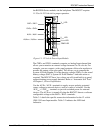
Using the PM-12, the ROC827 can accept 12 Volts dc (nominal) input
power from an AC/DC converter or other 12-volt dc supply. The input
source should be fused and connected to the BAT+ and BAT– terminals
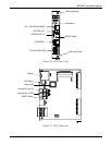
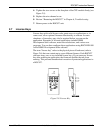
(see Figure 3-1). The base system (CPU, power input, and backplane)
requires less than 70 mA. The Power Input module economizes power
consumption using 3.3 Volts dc switching power that provides power to


