ROC827 Instruction Manual
Issued Mar-06 Power Connections 3-20
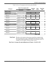
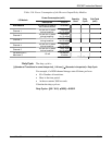
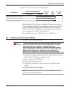
Table 3-16. Power Consumption of Other Devices
Power Consumption (mW)
Other Device
Description P
TYPICAL
Quantity
Used
Duty
Cycle
Sub-Total
(mW)
Total
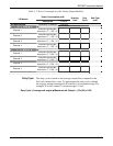
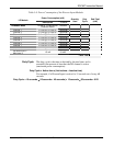
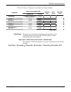
Although Tables 3-5 and Tables 3-6 through 3-15 take into account the
power the ROC827 supplies to its connected devices, be sure to add the
power consumption (in mW) of any other devices (such as radios or
solenoids) used with the ROC827 in the same power system, but which
are not accounted for in Tables 3-6 through 3-15.
Enter that Total value in the Other Devices line of Table 3-5.
3.3 Removing a Power Input Module
To remove the Power Input module:
Caution
Failure to exercise proper electrostatic discharge precautions, such as
wearing a grounded wrist strap may reset the processor or damage
electronic components, resulting in interrupted operations.
When working on units located in a hazardous area (where explosive
gases may be present), make sure the area is in a non-hazardous state
before performing procedures. Performing these procedures in a
hazardous area could result in personal injury or property damage.
1. Perform the backup procedure described in “Preserving Configuration
and Log Data” in Chapter 6, Troubleshooting.
2. Remove power from the ROC827.
3. Remove the wire channel cover.
4. Unscrew the two captive screws on the front of the Power Input
module.
5. Remove the Power Input module.
Note: If you intend to store the ROC827 for an extended period, also
remove the internal backup battery.


