


ROC827 Instruction Manual
Issued Mar-06 Power Connections 3-13
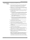
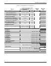
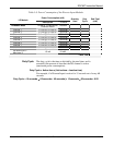
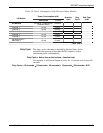
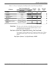
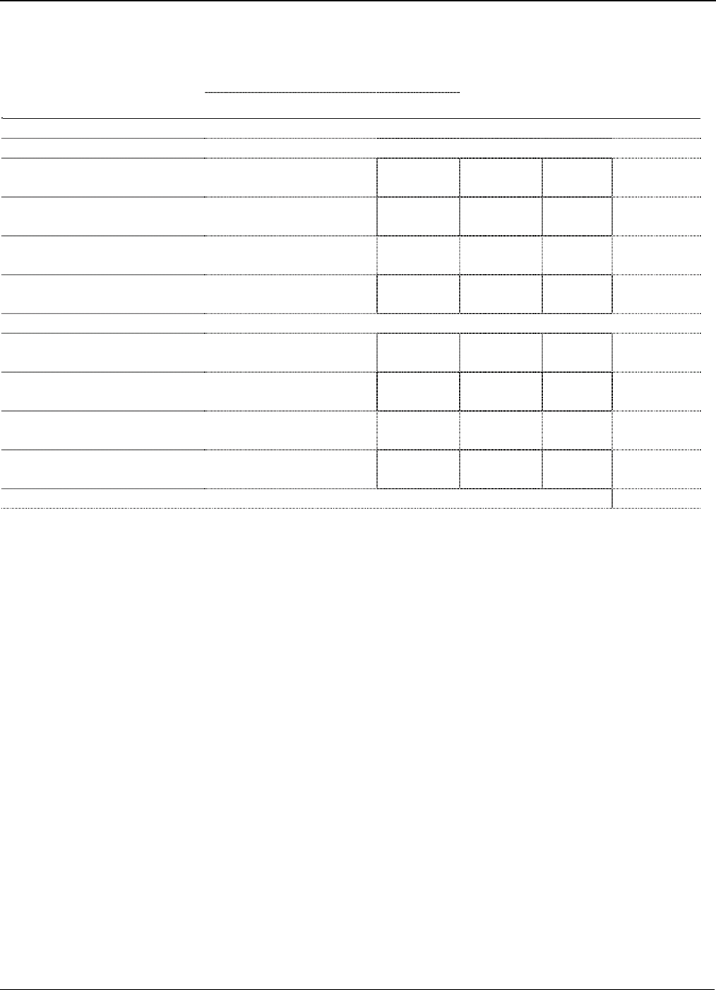
Table 3-7. Power Consumption of the Analog Output Modules
Power Consumption (mW)
I/O Module
Description P
TYPICAL
Quantity
Used
Duty
Cycle
Sub-Total
(mW)
AO Module Base
100 mA @ 12 volts dc 1200 mW
Jumper set for +T @ 12 volts dc
Channel 1
Channel’s mA current
draw from +T
*
1.25
*
12
Channel 2
Channel’s mA current
draw from +T
*
1.25
*
12
Channel 3
Channel’s mA current
draw from +T
*
1.25
*
12
Channel 4
Channel’s mA current
draw from +T
*
1.25
*
12
Jumper set for +T @ 24 volts dc
Channel 1
Channel’s mA current
draw from +T
*
2.50
*
12
Channel 2
Channel’s mA current
draw from +T
*
2.50
*
12
Channel 3
Channel’s mA current
draw from +T
*
2.50
*
12
Channel 4
Channel’s mA current
draw from +T
*
2.50
*
12
Table Total
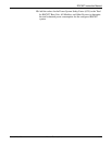
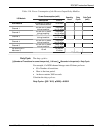
Duty Cycle
The duty cycle is based on the average current flow compared to the
full-scale current flow value. To approximate the duty cycle, estimate
the average current consumption in relation to its maximum range. For
example, if an AO channel’s current averages 12 mA:
Duty Cycle = Average mA output ÷ Maximum mA Output = (12 ÷ 20) = 0.60